

 Share This Page
| Home | | 3D Printing | | | | Share This Page |
A first-rate printer with a
serious vulnerability
— P. Lutus — Message Page —
Copyright © 2022, P. Lutus
Most recent update:
(double-click any word to see its definition)
Short biographical note: I have a substantial background in electronics. Among other things I designed high-efficiency power supplies for the NASA Space Shuttle. I say this because I get into some technical issues for which my technical background is essential to drawing any useful conclusions.
I'm publishing this Web page faster than I might under other circumstances, but for good reason: I have some warnings for new owners of this printer.
I'm an owner of the new Anycubic Kobra Max. My printer became inoperative after only a few days and I need to alert people to a vulnerability in this printer that, when properly guarded against, will protect the printer from itself and allow you to enjoy this printer's first-rate results and low price.
I want to emphasize this is not an indictment of Anycubic or their printers, and certainly not the Kobra Max, which produces very good results if set up and managed correctly. But there is a potentially fatal configuration error owners can make while readying the printer for use that can kill the motherboard without any warning.
So please — read on.
The Kobra Max has a very large print volume — 400mm wide x 400mm deep x 450mm high. That's really big for a printer that in early 2022 costs less than US$600.00. It has an automatic bed leveling feature that's easy to use and effective.
First Print: Benchy
I only finished a few test prints before the failure I describe below, but they show what this printer can accomplish. Here's a Benchy with default ABS settings and no special tuning:
Figure 1: Benchy, ABS, default settingsSecond Print: TPU Challenge
Okay, well, it seems everyone has a Benchy that makes a printer look good, usually after a lot of tuning (this didn't require any tuning). But there's a bigger challenge.
In a printer with a Bowden filament drive (not direct drive) setup, filaments like TPU can be a real test because of the long path between the drive motor and the hot end (flexible filaments are harder to control in a Bowden drive). Years ago I designed a TPU bike mirror mount, to be able to use an inexpensive bike mirror that comes with a perfectly terrible mount of its own. I've heard that TPU and other flexible filaments are super hard to use with Bowden drives and I wanted to see if this was so. Here's my bike mirror mount printed with the Anycubic Kobra Max:
Figure 2: My bike mirror mount, TPU, 215°C hot endI have to say I never saw such a clean TPU print of this part using the earlier direct-drive printer I describe here.
After these two test prints and before printing a larger volume model, I decided to optimize the printer's setup, flatten the print surface a bit, tune things for best performance. And make some mistakes.
The Anycubic Kobra Max has a removable glass print surface, 410mm (X axis) x 430mm (Y axis) in size, with a textured side that, at least for a while, makes use of bed adhesives unnecessary if not counterproductive. Replacement print surfaces are available, so if issues come up with the factory plate, they're easily resolved.
The operator is expected to use six metal clips to anchor the glass plate to a metal surface of the same size that contains the bed heating coils and thermistor. But ... wait for it, pilgrim ... how exactly one attaches the glass plate to the heating bed ends up being the difference between a terrific printer and a disabled one.
When I first saw the glass plate attachment diagram provided by Anycubic, I thought it was a mere suggestion and users had some latitude about how they chose to anchor the print surface to the heating bed:
Figure 3: Clips correctly placed — front & rear only, not along the sides.
(I added the green circles, they're not part of the original.)Anycubic also provides this diagram for attaching the clips themselves:
Figure 4: Right and Wrong clip Orientation
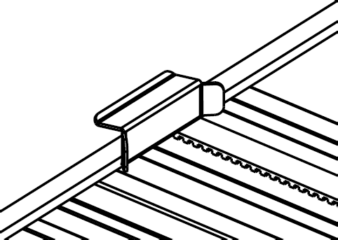
Wrong
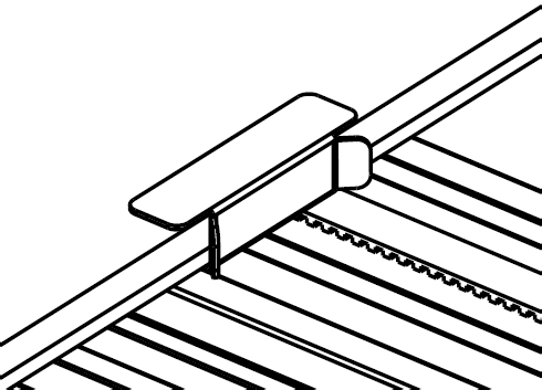
Right
When I first saw the Anycubic diagrams, I thought, "How weird — no support along the sides. Won't this cause a slight bow in either the glass plate or the bed?" And "That's funny — why would you want the large surface of the clips on top and the small surface on the bottom? This is probably not important."
So, with six provided clips and a naive outlook, I fastened the clips evenly around the print bed (top, bottom, sides), and with their large surface down — seemingly a better layout, but unlike Anycubic's pictures.
Premature Death
After a few more test prints, and after flipping the print surface to gain access to the kind of smooth glass surface I'm accustomed to using, the printer suddenly died with this message:

Figure 5: Bad News
This means the motherboard can't detect the thermistor any more and (obviously) won't heat up the print bed without a working sensor.
Analysis
I checked the thermistor, which was reading correctly all the way to the motherboard, and the heating element, the same, so I was pretty quickly forced to the conclusion that the motherboard suffered some kind of fatal damage.
Over the next few days I figured out what happened:
- The print bed/heating element has one metal side and one printed-circuit-board side.
- The printing surface should be attached to the print bed using the clips described above and as shown in Figure 3.
- But if the clips are attached to the sides of the print surface, unlike Anycubic's layout diagram, and in particular if they're attached with the large side down, they may short out the heating element or connect its 24 volt power to the thermistor — or both.
Here's a picture of the underside of the print bed — the printed-circuit side — with a clip in place to show what can go wrong:

Figure 6: Clip, side placement, overlapping 24 volt heater circuit board trace
NOTE: Don't do this, ever.
Figure 6 shows a clip located along one side of the print bed, an area Anycubic avoids in its pictures. Also, this clip is pressed in place with the large side down, which makes things worse (more circuit trace contact area between the clip and the board). Again, that's a 24 volt bed heater trace the clip is scraping against, a recipe for trouble.
It turns out that the heated print bed metal surface isn't connected to ground anywhere (it rides on a series of rubber wheels), which means if one or more clips are positioned as shown in Figure 6, the entire print bed can be elevated to 24 volts from a high current source. Very bad.
The front and rear of the print bed have more safety margin between circuit traces and clips:

Figure 7: Clip, rear edge placement, adequate margin to circuit board trace
But it's important to add that, if the clips are attached incorrectly — large face down (Figure 4) — they may in some cases short out the thermistor circuit board traces.
I ended up waiting a long time for promised warranty parts from Anycubic — the details:
The good news: I reported this failure to Anycubic, who after hearing my analysis quickly agreed to ship a motherboard and print bed under warranty.
The bad news: Parts shipment required over two months to complete.
The explanation: after a week went by I realized something was going wrong with the warranty service, which I am sure Anycubic wants to honor:
Worldwide integrated circuit shortage: this has affected any businesses that rely on integrated circuits — automobiles, both conventional and electric, consumer and industrial electronics — and there's no immediate relief in sight.
Coronavirus lockdowns: As I write this, several Chinese cities are in total lockdown, including Shanghai (BBC: Shanghai Covid lockdown extended to entire city). I don't know where Anycubic's factory is located but either the primary factory or some of its suppliers (or both) are surely crippled by the lockdown.
So I was annoyed but not surprised by the delay. I'm sure Anycubic will do all in its power to honor its warranty, given that this is a first-rate product that has much future potential in its price range.
About the mispositioned metal clips and the motherboard failure, when I was younger I was able to kick myself in the butt directly, without falling down. Now I'm older and have a harder time performing that maneuver, but I get into just as many cases where I want to. This is definitely one of those cases.
Before using it, I could have carefully examined this printer and discovered its flaw, its Achilles' Heel, and acted to avoid it.
But Anycubic needs to emphasize the risk of motherboard failure if the print bed clips are mispositioned. Not enough emphasis is given to this very real possibility of failure. The clip-placement picture (Figure 3 above) isn't obviously a warning, more of a suggestion.
Follow the Anycubic-provided diagrams exactly:
Don't put print bed anchoring clips along the sides of the heated print bed. Front and rear only — see Figure 3 above.
Clips large side up, small side down — see Figure 4 above.
Be careful with metal objects near the heated bed. Don't leave tools or clips lying around where they might make contact with the heated bed's printed-circuit-board underside.
An unrelated suggestion: before using this printer, tighten all the hardware, not just the parts you assembled. Go through the entire printer, make sure all the hardware is snug. I suggest this because many of the preassembled parts of my printer seemed to have been assembled by someone with very little upper body strength.
Again, this is a very good printer, once this article's issues are addressed.
| Home | | 3D Printing | | | | Share This Page |


