

 Share This Page
| Home | | Programming Resources | | Home Automation | | | | Share This Page |
(double-click any word to see its definition)
On this page I will describe the procedures — and some of the risks and problems — you will need to know while installing an Insteon system.
WARNING: First and foremost, if you are not handy with tools and electrical systems, please ... hire an electrician instead of trying to undertake this task yourself. And have the electrician read this page for specific cautions and advice. I offer this advice because a house electrical system can kill the unwary. You've been warned.Okay, warning given. From this point onward, I will make the assumption that my readers are (1) homeowners skilled with electrical systems, (2) professional electricians, or (3) curious people who just want to read the article but who aren't planning to self-administer shock therapy.
Scope and Limitations
My Insteon system is limited in scope — I have only relay controls (primarily 2466SW units) and no dimmers because my system is almost entirely compact fluorescents. This means these instructions won't cover all possibilities — a typical installer will need to include some things I don't use. But this article will educate you in the basics and get you started. Also, in a later section, I describe in detail what I regard as the heart of a sophisticated Insteon system — a system controller with enough brain power to make the entire system modestly intelligent.
Overview
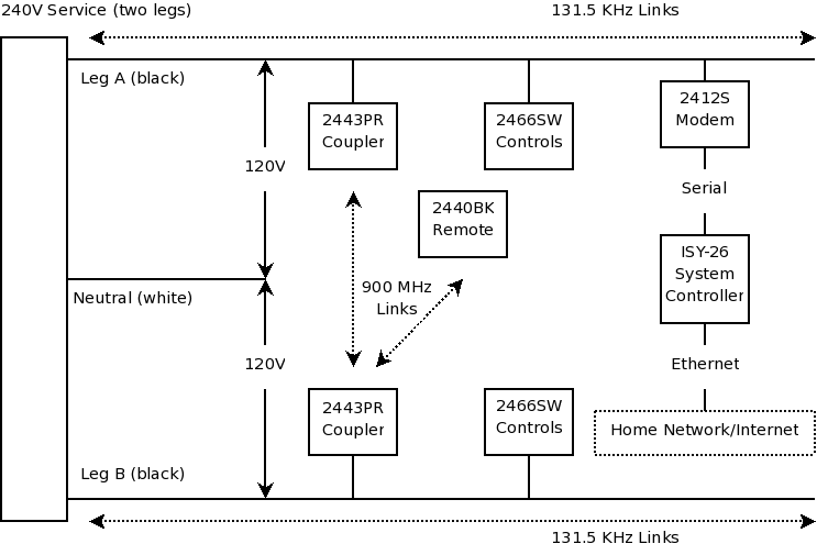
The first step in this process is to acquire a mental picture of a normal Insteon system. It typically consists of:
Here are some points about the above list:
I want to emphasize these points to avoid creating the impression that you must have a modem and a system controller to use an Insteon system — you don't. I think a system controller is a very nice addition, but it's not a requirement.
Installing a switch
WARNING: Again, unless you are handy with tools and are familiar with home electrical systems and their risks, don't undertake this kind of work — hire an electrician.This section will show the simplest installation activity, that of wiring an Insteon switch into place. You will be performing many repetitions of this activity, and for a number of reasons it is essential to learn how to do it properly.
Some readers may wonder why I go into such detail about this — after all, isn't it true that if you get it wrong, if you don't connect it just so, or if you don't tighten the wire nuts snugly, the switch simply won't work, and you can try again? Well, no, as it happens, with three-wire Insteon (and X-10) controls, it's a bit more complicated than that — you can very easily destroy the control, in particular if the neutral (white) connection is not made securely and correctly.
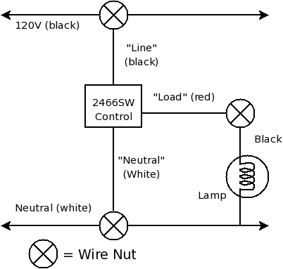
Insteon Switch Wiring Diagram
|
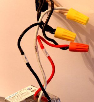
Typical installation
|
Here is a step-by-step installation procedure:
Repeat the above procedure for as may Insteon controls as you intend to install, but remember that you may move from an electrically disabled location to an enabled location without realizing it. Not all of us have the luxury of shutting the entire house down — remember to test before touching.
Paired Controls
Nearly all houses have light switches that are expected to operate in tandem, such as at each end of a long hallway, or on a staircase, where each end of the passage has an independent light switch. The older X-10 controls had a special satellite switch for this case, but Insteon controls handle this in a different (better) way — they have just one kind of control, and the connection between two ends of a passage or staircase is made using computer logic rather than wires. The advantages should be obvious — you only have to buy one kind of control for all locations, and better, if you want more than two controls to operate together (such as a large room with three or more light switches), this is easily accomplished.
If you have a location where two separate switches operate in tandem on the same load, simply wire one of two Insteon controls into whichever electrical box contains the load wire as shown above, then install a second Insteon controller in the other box, connecting the "Line" (black) and "Neutral" (white) leads, but with no load connection (put a wire nut over the red "Load" wire to prevent an inadvertent short-circuit).
Yes, I know this sounds crazy at first glance — how can the second switch do its job without being connected to the load? Well, Insteon controls are pretty clever — you can make one control act in concert with another, even if only one of them is actually connected to the intended load. The only requirement is that both controls need to be powered — they should both have their "Line" (black) and "Neutral" (white) wires connected. Only one of them needs to have a "Load" connection.
Later on I will explain how to tell two or more controls to work as a team.
Access Point / Wireless Phase Coupler
This page deals with hardware installation issues, and the placement of two wireless access points is one of the last physical installation issues (most of the remaining activities involve configuration and software activities).
As explained above, the wireless access points (2443PR) serve two purposes — they open a communication pathway between the two house wiring legs, and they grant Insteon remote controls access to the house system.
Access point installation is relatively simple:
Now we can turn to configuration issues and programming.
| Home | | Programming Resources | | Home Automation | | | | Share This Page |