

 Share This Page
| Home | | Computer Graphics | | Adventures in Ray Tracing | | | | Share This Page |

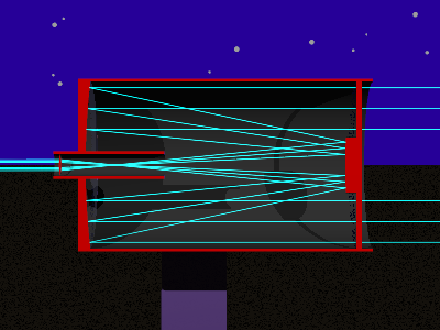
Cassegrain telescope cross-section
|
|
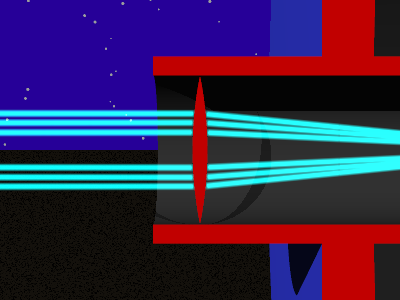
Close-up of eyepiece area (note central obstruction)
|
|

Direct view of target
|
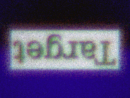
Eyepiece view of target
|
Eyepiece focus animation (click to replay)
|
|
This telescope design represents a big leap in sophistication from the Galilean telescope of the previous page, and it represents the passage of many years in the history of astronomy and telescope design. In fact, this design is (more or less) one example of the sort of telescope presently owned by many advanced amateur astronomers as well as professionals. Please refer to the graphic images on this page. In this design:ConclusionThis design has many advantages over the prior design and is regarded as an advanced optical configuration, suitable for astronomical observation and photography. It hews to a basic optical principle by using an absolute minimum number of lenses. It is very difficult to control the various distortions caused by lenses in the optical path of a large-aperture telescope, and it is preferable to do nearly everything with mirrors. In fact, in many photographic applications, the eyepiece lens is eliminated and an image sensor (film or CCD) is placed at the focal point instead. My version of this design differs from a typical Cassegrain that one might purchase from a commercial builder of telescopes. In a commercial Cassegrain design (called a "Schmidt-Cassegrain"), a spherical primary mirror is used instead of parabolic, because spherical mirrors are much easier to figure, and the glass plate to the right is shaped to create the optical behavior that would have been obtained with a parabolic mirror. Overall this reduces the cost of manufacture, and the glass plate has the added purpose that it prevents entry of dust into the telescope. I own a 10" Schmidt-Cassegrain made by Meade and I have done quite a lot of observing over the years, so I am familiar with the various optical aspects of the design. Consequently I know when my virtual telescope is successfully imitating a real one. In creating a modern, virtual telescope like this, I had to overcome various problems. The primary problem was sorting out the various focal lengths so that a focused image would be present at the eyepiece. Another problem, one I had not anticipated and that I had some difficulty sorting out, was that in this telescope design there is an obstruction (caused by the secondary mirror) in the middle of the field of view. I found that if I simply centered my virtual camera along the eyepiece line, the image would be blocked by this obstruction. I knew I had performed all the required calculations, and there should have been a focused image where the camera was located. I solved this problem by using one of the more advanced features of POV-Ray called "focal blur." The original purpose of focal blur was to create the effect one sees in photography when using a camera with a relatively wide aperture. Under these conditions, objects at only one distance are in proper focus, objects at other distances are blurry. It turns out that POV-Ray accomplishes this effect by shooting many random rays from the confines of a user-determined circular aperture and summing the results. The user gets to specify the aperture (in essence the diameter of a lens) as well as the location of a plane at which all the rays cross. The latter becomes the focal distance. Using focal blur solved several problems. I was able to specify an aperture larger than the central obstruction, making it possible to create an image just as our eyes do (by integrating light rays across a given aperture), and I was able to specify various focal distances to imitate various eyesight conditions and their results in the overall design. Here is my POV-Ray eyepiece-camera definition that includes the needed focal-blur specifications:
- Light from a viewed object enters from the right, passing through a glass plate,
- is reflected from a large parabolic mirror at the left end of the tube,
- is reflected once again from a smaller spherical mirror at the right,
- comes to a focus near the eyepiece lens at left center,
- and is presented to the viewer by way of the eyepiece lens.
The specifiers relevant to focal blur appear at the bottom of this listing, starting with "Aperture." I normally choose an aperture similar to the aperture of the eyepiece lens, and a distant "focal point" to model the subjective visual experience of a human observer with normal eyesight. We turn now to the target and eyepiece graphic views. Note the crystal-clear target view, rendered by simply pointing a virtual camera at the target and choosing a suitable view angle. Then note the view of the same target through the virtual telescope (note that, because the objective focal point is in front of the eyepiece lens, the image is correctly rendered upside-down). On comparing these views, the reader may wonder what purpose the telescope serves, since the direct view is perfectly clear. But remember, the goal of this project is to simulate a real optical system, warts and all, perhaps with the aim of optimizing the design before building an actual telescope in the non-virtual world (otherwise known as "reality"). Also, it is important to remember that the perfectly clear target view only exists in our virtual world because normal physical laws are disregarded for that view, while a number of optical limitations are being reasonably simulated in the eyepiece view. Those who have telescope design experience will immediately recognize that the color distortions in the eyepiece view arise from the use of a plain eyepiece lens without any effort to correct for chromatic aberration (and as demonstrated and explained in the prior telescope page of this section). In fact, this view is uncannily similar to a typical, real-world view, at high magnification, looking through an eyepiece made of one or more uncorrected lenses. This effect is achieved in POV-Ray by entering a suitable value for "dispersion" in the "interior" block of the eyepiece lens. As one would expect in a real optical system with the properties this one has, the position of the eyepiece lens is critical, and moving this lens produces exactly the effect one would see in a real telescope. To see the effect of moving the eyepiece lens, click the eyepiece focus graphic on this page to replay an animation that does just that (and note that I disabled the above-described dispersion effect for this animation to avoid incredibly long rendering times). Here are the POV-Ray source files for various aspects of this project:camera { //*PMName Eyepiece Cam perspective location <0, 46, -10> sky <0, 0, 1> direction <0, 0, 1> right <1.3333, 0, 0> up <0, 1, 0> look_at <0, 46, 1> angle 4 aperture 1.6 blur_samples 20 focal_point <0, 0, 100000> confidence 0.9 variance 0.008 }Remember about these POV-Ray source files that, as in the prior telescope example, they require a TrueType font to render the target's text correctly.
- Cross-sectional view of telescope
- Closeup of eyepiece area
- Eyepiece view of target
- Eyepiece focus animation source
This page shows how telescopes and other optical systems will be designed in the future. As the cost of computer hardware and software continues to fall, at some point an economic threshold will be crossed, after which it will seem wasteful not to model even sophisticated, complex designs in an interactive environment like POV-Ray and an appropriate modeling front end. One change I look forward to is an improvement in rendering times. The images on this page were assuredly not rendered in a flash, and considerable patience is required to do this sort of work using present-day personal computers. I expect this will change as time passes. But, on contemplating increases in processing speed, I am reminded of "Wirth's Law," put forth by Niklaus Wirth in 1995. It says:"Software gets slower faster than hardware gets faster."A program like POV-Ray is a perfect demonstration of this law, because it seems always to need more computer horsepower than you have, no matter who you are or what hardware you have. It seems inevitable that, upon upgrading, you immediately think of a new, ambitious ray tracing project that brings your new system to its knees.
| Home | | Computer Graphics | | Adventures in Ray Tracing | | | | Share This Page |