
 Share This Page
| Home | | Raspberry Pi | | | Share This Page |

Copyright © 2016, Paul Lutus — Message Page
Most recent update: 03.11.2016
(double-click any word to see its definition)
Disclaimer
Notwithstanding my use of the Raspberry Pi name and icon, I have no connection with the Raspberry Pi Foundation. I'm just a big fan of their work.
Video
See an abbreviated video version of this content on YouTube: Setting up the Raspberry PiHardware
The Raspberry Pi continues — perhaps I should say exemplifies — a long-term trend toward more computing power, in a smaller space, at a lower price. Although this article focuses primarily on the Raspberry Pi 2 model B (background) priced at US$35.00, there now exists a smaller, cheaper version called the Zero, which at the time of writing costs US$5.00 (if only people could get their hands on one). It's so cheap that a British technical publisher recently gave thousands away attached to copies of their magazine.
Young people may not find this situation as astonishing as I do, so I ask my readers to imagine this from my perspective. When I was young, for all practical purposes computers didn't exist. My first exposure to computers came during a charitable event hosted by a local IBM facility, during which the company donated outdated or worn computer parts to schools. On this occasion I acquired a memory module that included a vacuum tube* internally composed of two triodes (each of which in modern times would be a transistor), a device that could hold one bit of information so long as power remained available.
The device was roughly cylindrical, about six inches (15 cm) long and, apart from the vacuum tube, contained about 10 parts — resistors and capacitors responsible for stabilizing the single binary bit the device held. It weighed about four ounces (114 grams) and required about five watts of power (remember that vacuum tubes need significant energy to heat up their cathodes sufficiently to emit electrons). At the time I acquired this device (and conveniently overlooking the fact that I only acquired it because it had stopped functioning) I imagined having eight of them and designing a binary counter able to count up to 28 (256).
I've managed to locate a picture of the device I'm describing:
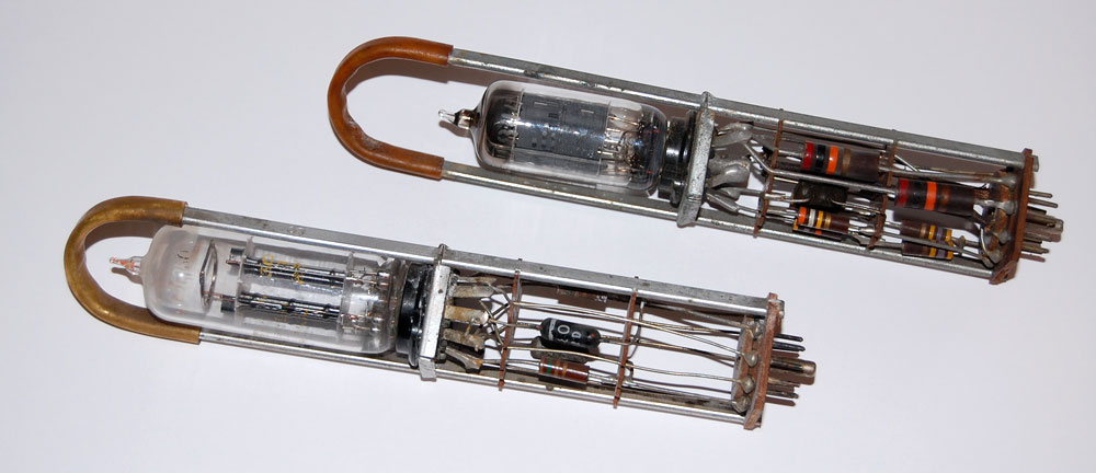
Figure 1: Early vacuum-tube memory modules (ca. 1955)
These devices were so unreliable that they included a convenient handle, so an overworked technician could pluck it out of the machine and replace it, after perhaps 200 hours of service.
I eventually stopped thinking about building a computer, tore the discarded memory module apart and (along with parts from a broken TV set) turned it into a ham radio transmitter.
For the next several decades, as an aerospace engineer I acquired math results with a slide rule and continued to dream of having a computer. Then, in 1977, it became possible for an individual to own a computer — the Apple II made its appearance and I acquired one. Here's a picture of that system when it was new:
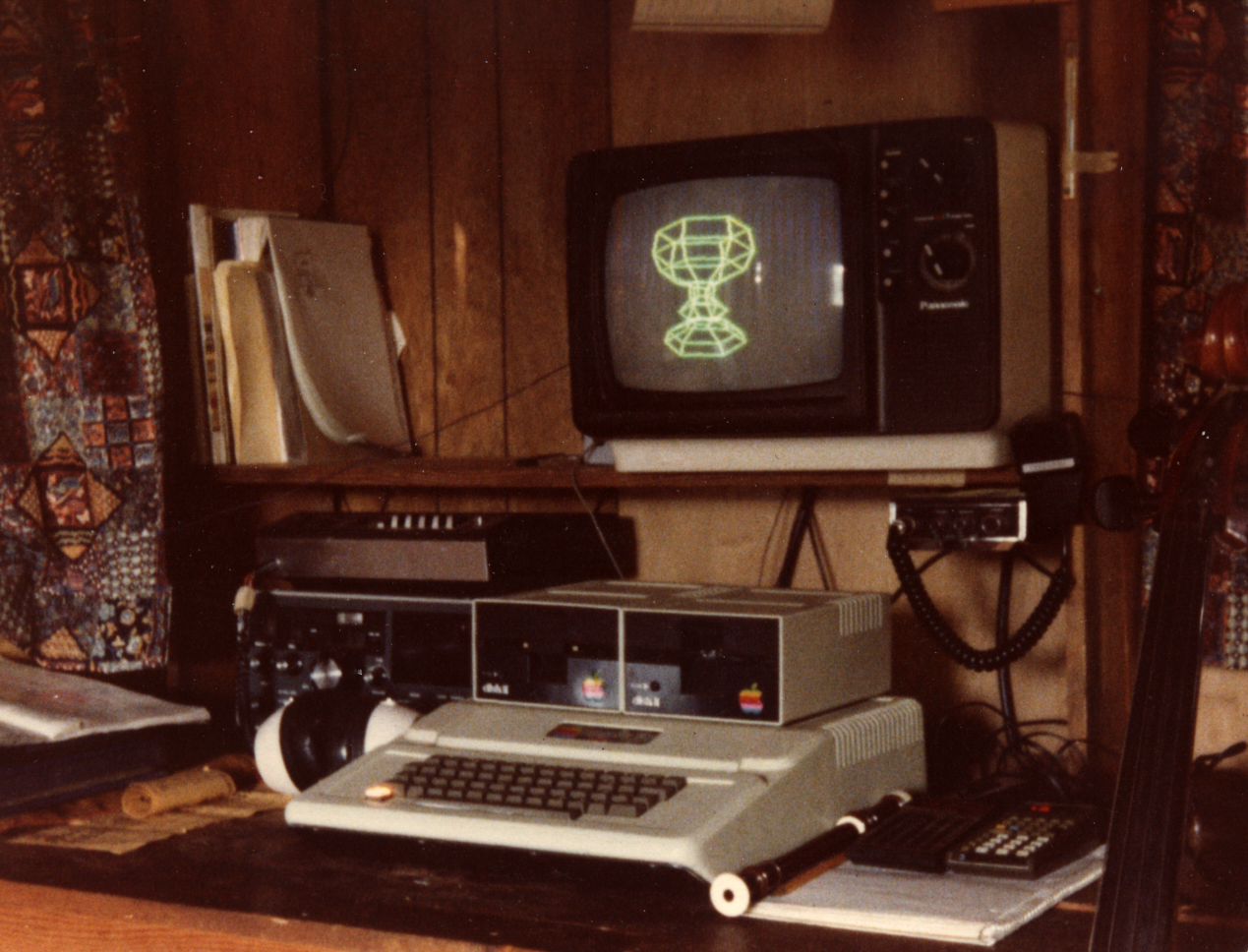
Figure 2: My first computer (1977)
Now for the point of this narrative. The Apple II I so eagerly acquired in 1977 had a 1 MHz clock, four kilobytes of RAM, and cost US\$1600.00 in 1977 dollars — that's US\$6400.00 in adjusted 2016 dollars. For comparison, the Raspberry Pi Zero has a 1 GHz clock, 512 MB of RAM and costs US$5. Overlooking some subtle apples/oranges issues, the Raspberry Pi Zero comes out way ahead of my Apple II:
\begin{equation} rv = \frac{ca\, ra\,pb}{cb\, rb\, pa} = \frac{1^9\, 5.12^8\, 6400}{1^6\, 4.096^3\, 5} = \frac{3.2768^{21}}{2.048^{10}} = 1.6^{11} \end{equation}In this comparison, the Zero's value is essentially uncomputable* when placed alongside my original Apple II. And someone is giving it away attached to a magazine.Where:
- $rv$ = relative value
- $r$ = RAM
- $c$ = clock
- $p$ = price
Software
With respect to operating systems, the Raspberry Pi computers don't run Windows, they run Linux. There are several reasons:
- Desktop Windows is too big to fit in a small computer's storage or memory.
- Windows can't be made significantly smaller without ceasing to provide an experience recognizable to a Windows user.
- Compared to Linux, Windows is far too expensive for the value it offers.
(On reading this, someone will surely point out that a version of Windows 10 runs on the Raspberry Pi, but it's not quite so — look more closely at this claim.)
During my time in the computer field, and at risk of understatement, computer hardware has gotten less expensive and computer software has gotten more expensive. The former trend results from a gradually improved understanding of computer technology, materials and what nature will permit. The latter trend results from the existence of Microsoft.
Early in human history, print literacy was a specialty practiced by few. If you wanted to communicate something in writing, you consulted a monk, who would render your thoughts on parchment for a fee. Eventually a spoiler came along and invented the printing press, which led to cheap books, which led to widespread literacy, after which monks were heard insisting that they didn't really care about filthy lucre anyway.
Many people don't realize that the present moment — in which people are beginning to write their own software — had a historical parallel in which people began to write their own documents. Widespread print literacy required that the raw materials become less expensive, along with wide public acceptance of the heretical notion that people should be able to read and write their own documents. In the same way, widespread computer literacy will require that the raw materials become less expensive, along with wide public acceptance of the heretical notion that people should be able to read and write their own computer programs.
I haven't decided whether Linux, or the Raspberry Pi and its many imitators, stands for the printing press in this historical comparison, and maybe it's both. But there's one perfect parallel — people who don't understand computers will be seen as illiterate and be left behind.
Information
The print revolution changed people's relationship with information. Over time there came to be more ways to reliably find things out, and less dependence on rumors and barely coherent narratives. The computer revolution continues this trend, primarily by increasing the velocity toward either perfect understanding or perfect incomprehension. I think there will always be people held hostage by ignorance, and the only change created by computers for such people is the speed with which they craft a bulletproof fantasy world in which to live. But in the lives of those intent on actually finding things out, the computer is a useful and powerful tool, able to produce trustworthy logical and mathematical results if fed reliable data.
Based on the amount of information now at our fingertips, one might be inclined to say that everything is known and there are no new frontiers to explore. But the same computer power that provides vast quantities of information also reveals what we don't know. As just one example, of the mass-energy in the universe surrounding us, we only understand 4.6% of it (and that not very well). The remainder of the universe is a complete mystery, and an enticing frontier for young scientists.
In modern physics, because of its reliance on mathematics (and because nature appears to be innately mathematical), the computer plays an increasingly important role in constructing and testing theoretical models. In fact, it was by noting discrepancies between supercomputer models and observations of nature that we formulated our current ideas about dark matter and dark energy.
Some of my readers may wonder how a discussion of supercomputers fits into a discussion of small, cheap computers like the Raspberry Pi. Well, as it happens, because of certain physical limitations of computing hardware and speed-of-light communication issues, it's more efficient to solve certain kinds of problems in parallel than sequentially. Such a problem is most efficiently and economically solved, not with a single superfast computer, but with a large number of relatively simple, cheap computers working in parallel.
Consider weather forecasting. Modern weather forecasts rely on a particular kind of mathematical model in which the atmosphere is segmented into a great number of interacting cubes of air. As the model runs, each cube is evaluated with respect to the cubes around it, for a chosen interval of time. Then the process is repeated for another interval of time, ad infinitum. Eventually someone realized that, instead of serially computing new results for 100,000 cubes of air using one processor, it would be much more efficient to acquire 100,000 processors and assign a cube of air to each of them, to be solved in parallel. This conceptual breakthrough literally speeds up such a process 100,000 times.
Whether modeling a cluster of stars, the orbits of the solar system's planets or producing a weather forecast, most theoretical models can be computed in parallel. Modern supercomputers work just this way, and these computers are assembled out of many relatively simple processors, one processor to a board, in a vast array of interchangeable circuit boards — little computers like the Raspberry Pi.
This article isn't just a philosophical reflection — in this article I'll show how to acquire a Raspberry Pi and prepare it for use. Here are the steps:
Acquire
This is perhaps the least detailed part of the process, since I don't like giving directions that sound like commercial promotions. I'll trust my readers to use their own methods to acquire a Raspberry Pi, but I should say that these instructions assume readers have acquired a Raspberry Pi 2, model B, although the same instructions should work for earlier and later models with small changes in procedure.
Prepare
In this step, we will format a memory device called a micro SD card and populate it with a free operating system suitable for the Raspberry Pi — a version of Linux called "Raspbian". This step is needed because the Raspberry Pi has no built-in operating system, it must be provided with one.
Although a bit of an idealist, I'm aware that most of my readers run Windows on their primary computer, so I'll explain how to prepare the SD card using Windows as well as Linux.
- Acquire a micro SD card. The highest priority is that it read and write data fast, a secondary but important consideration is that it have adequate storage space (8 GB or greater). Here's a list that compares micro SD cards with respect to read/write speed. Also, be careful — an SD card isn't necessarily a micro SD card. The latter are very small, and the most recent Raspberry Pi models only accept the micro size.
Prepare and populate the micro SD card:
Linux (this example was created on a Linux Mint installation):
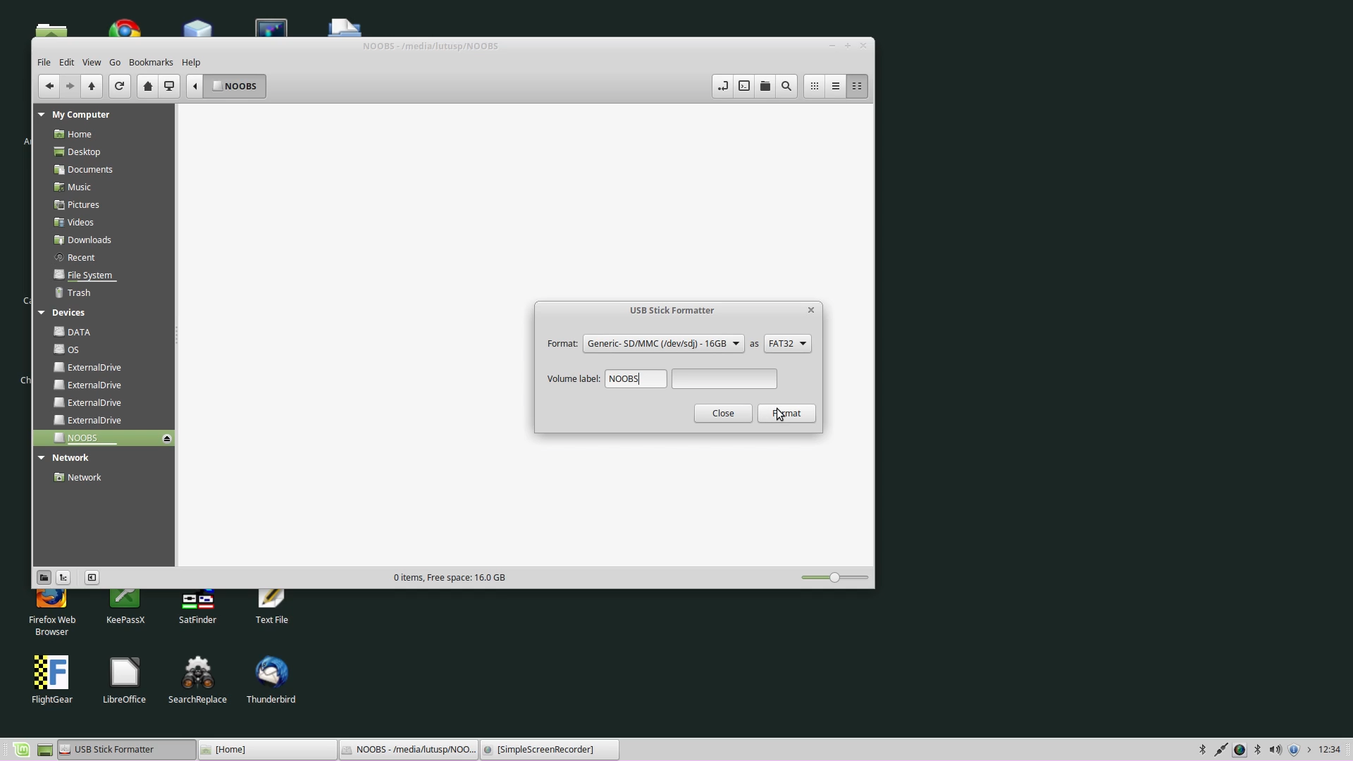
- Insert the micro SD card into a Linux desktop or laptop computer.
- To be sure the card is ready for use, format it:
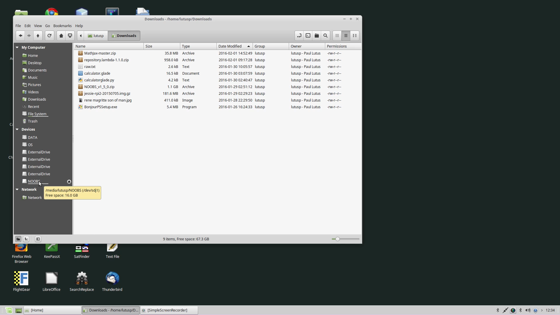
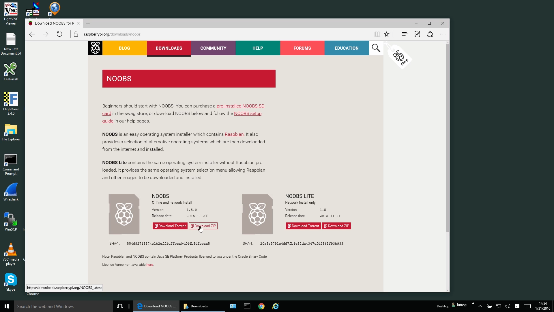
- Acquire a copy of NOOBS from this Web page — choose the Zip file version(graphic) and download it.
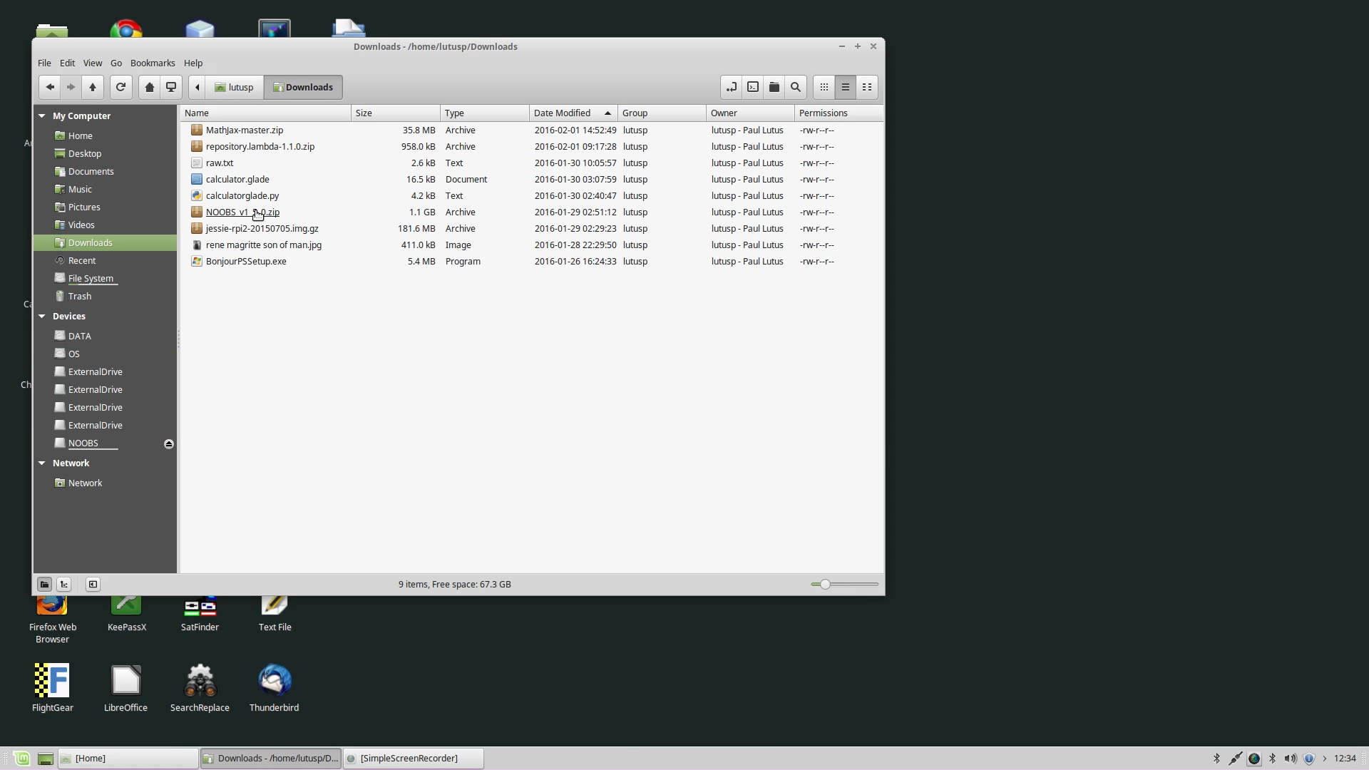
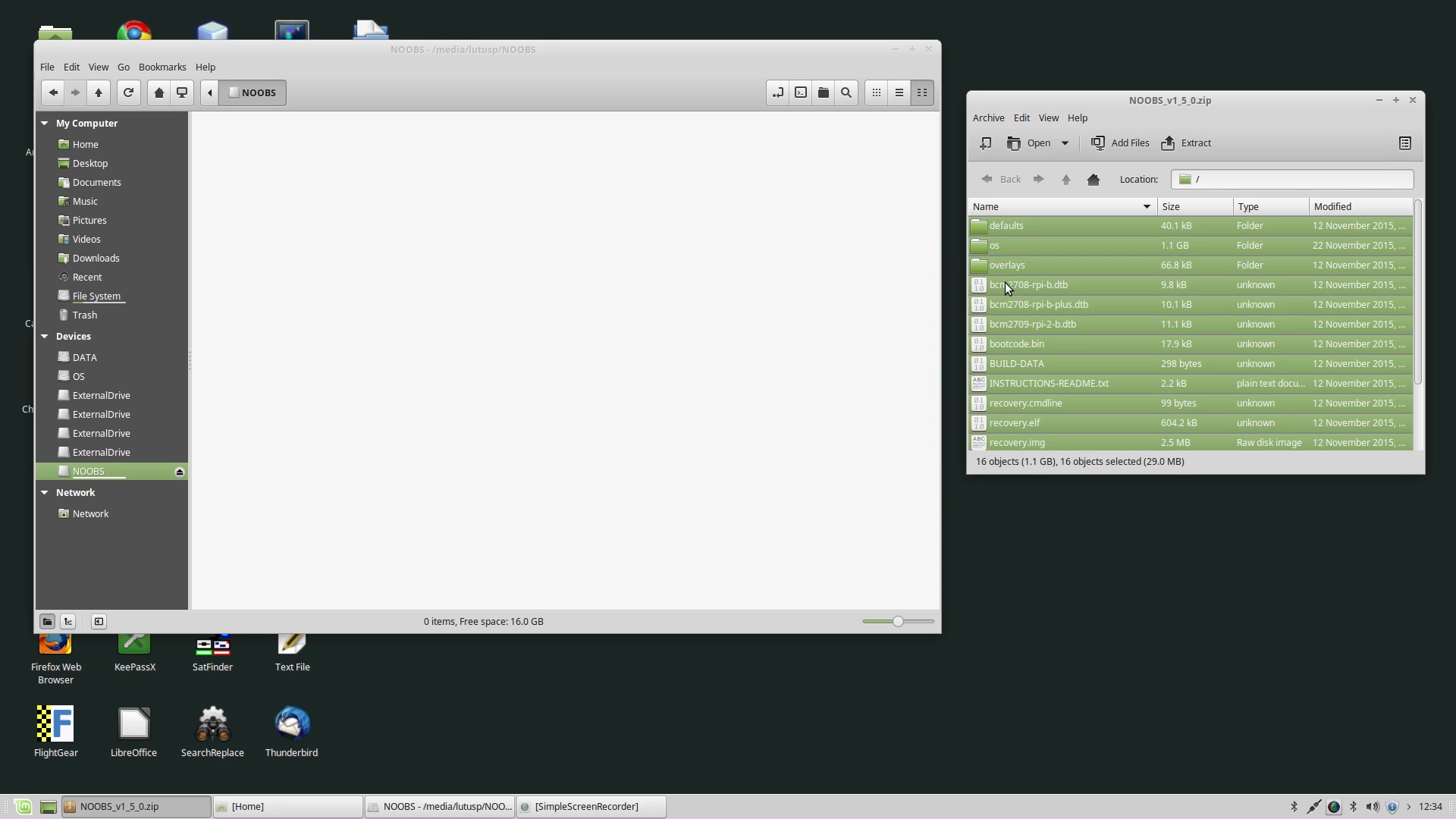
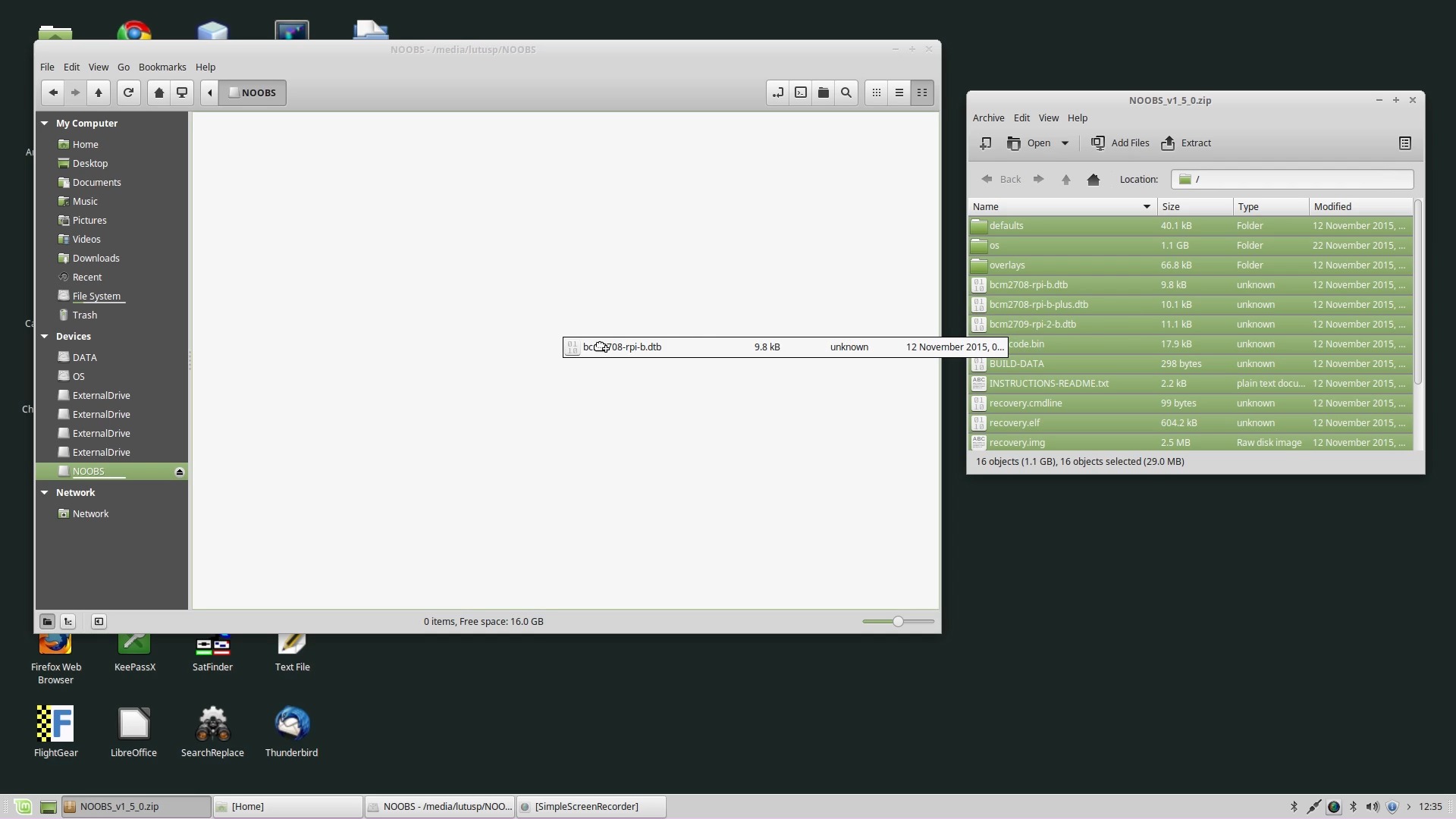
- Locate the downloaded Zip file in your system's downloads directory(graphic) and click it to reveal its contents(graphic).
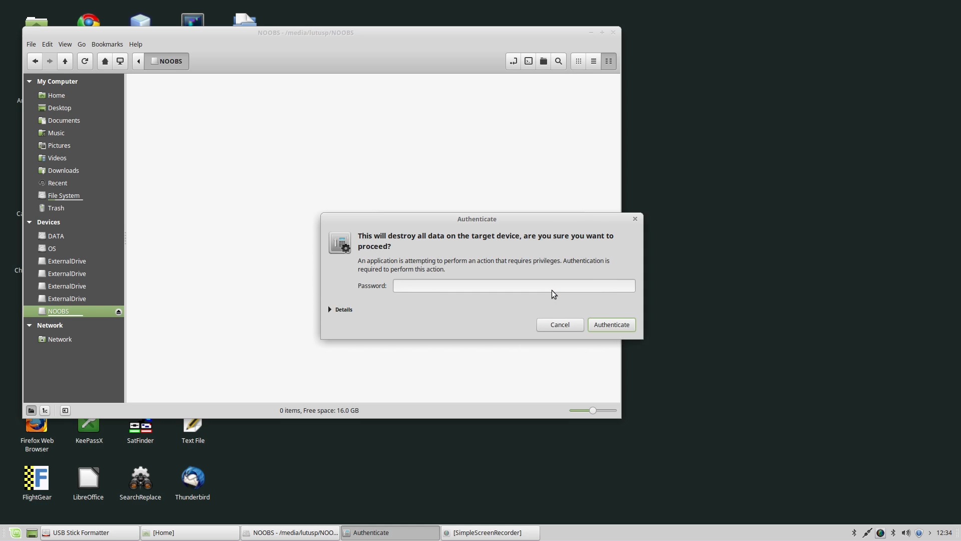
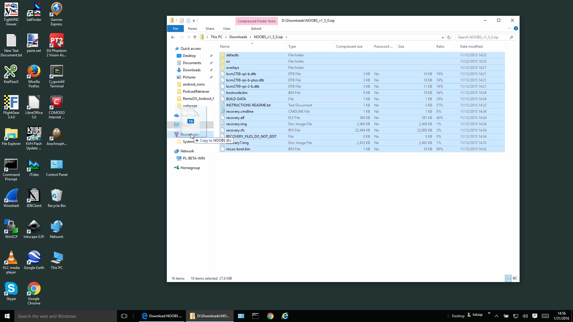
- Select all the contents of the Zip file(graphic) and (by dragging and dropping) copy those contents onto the SD card(graphic). Be sure you're copying the Zip file's contents, not the zip file itself.
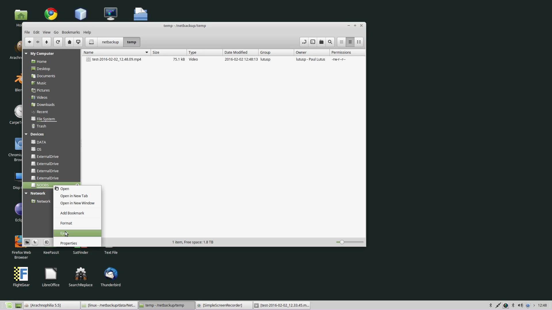
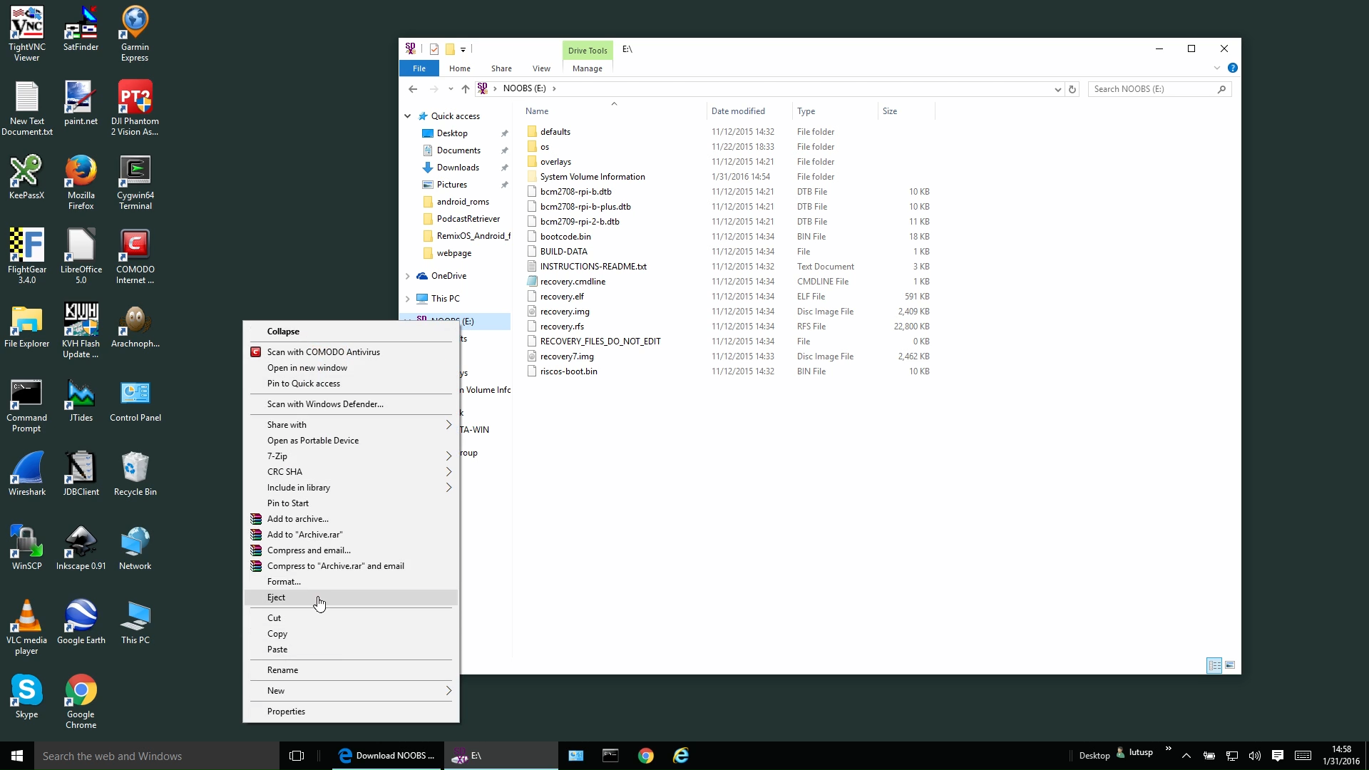
Eject the SD card from your computer — don't just remove the card, tell Linux to eject it(graphic) (this assures that the card has been fully written to and closed).Windows (this example assumes Windows 10):
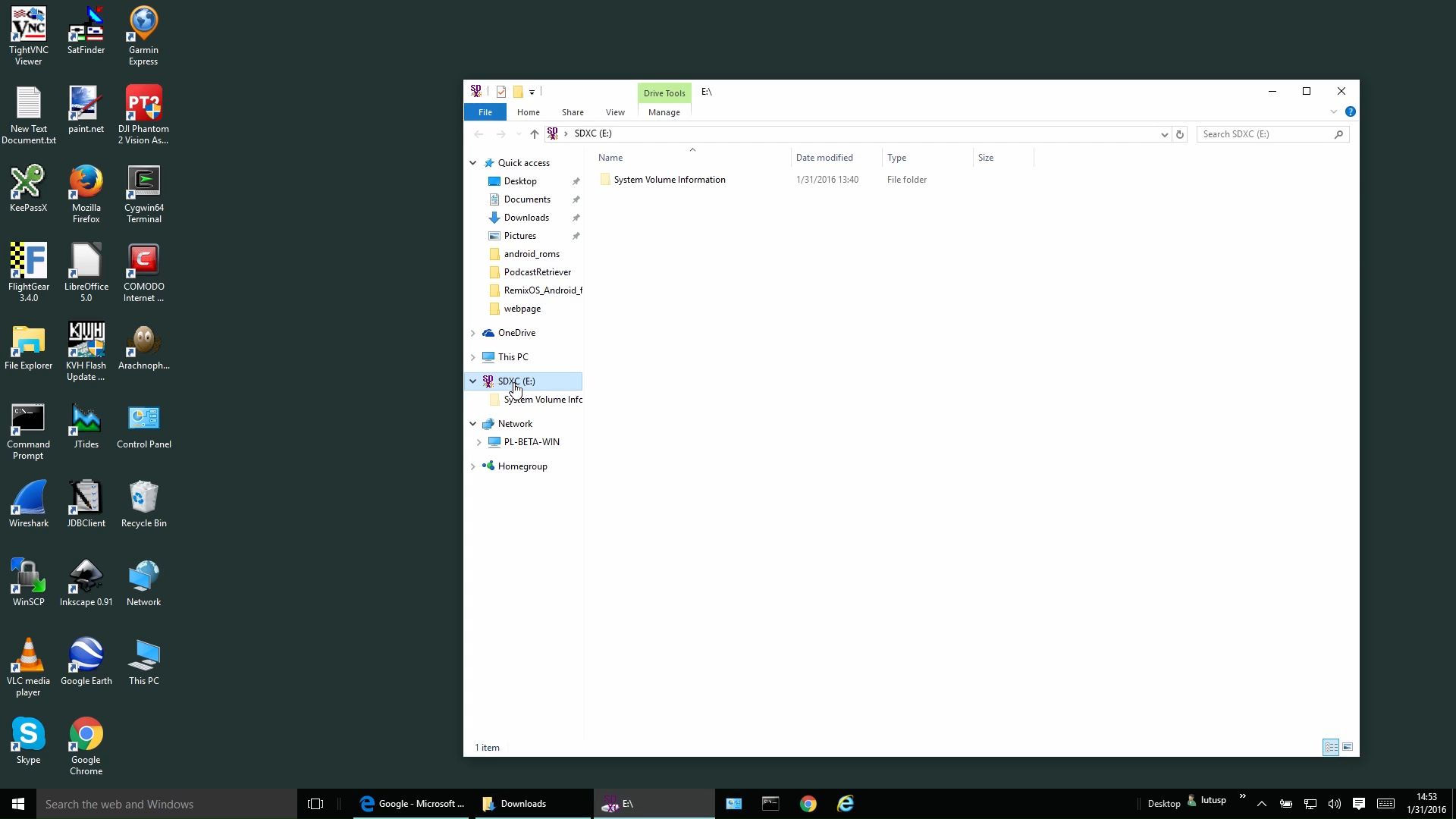
- Insert the micro SD card into a Windows desktop or laptop computer.
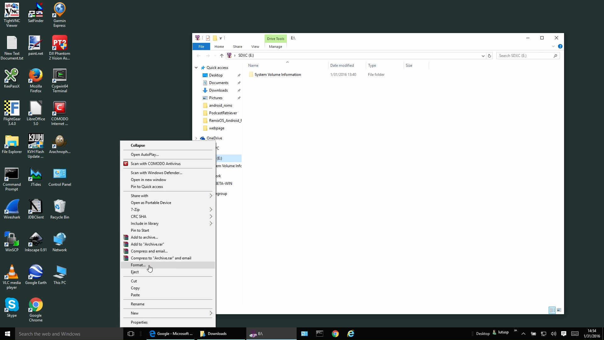
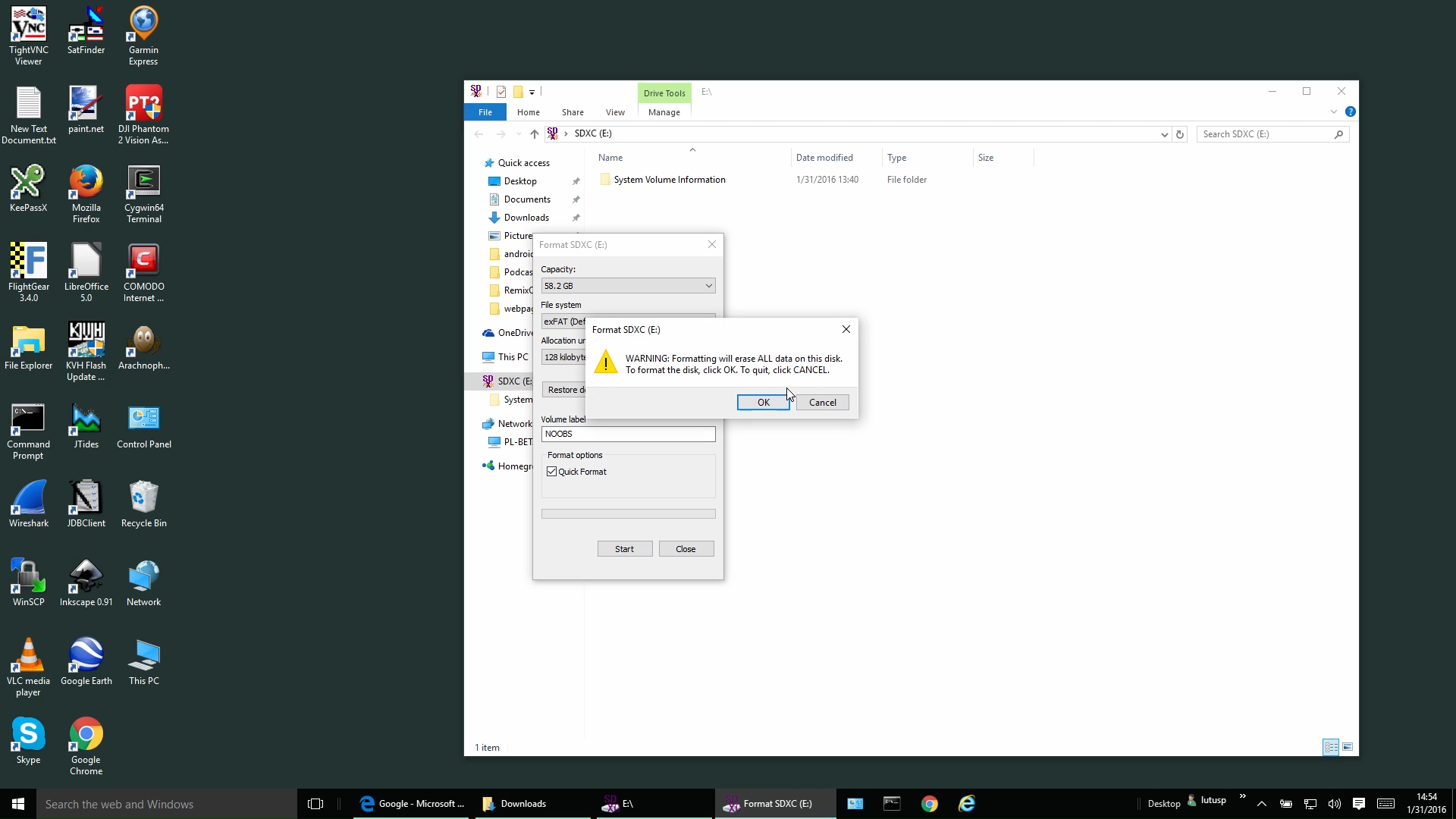
- To be sure the card is ready for use, format it:
- Download a copy of NOOBS from this Web page — choose the Zip file version(graphic).
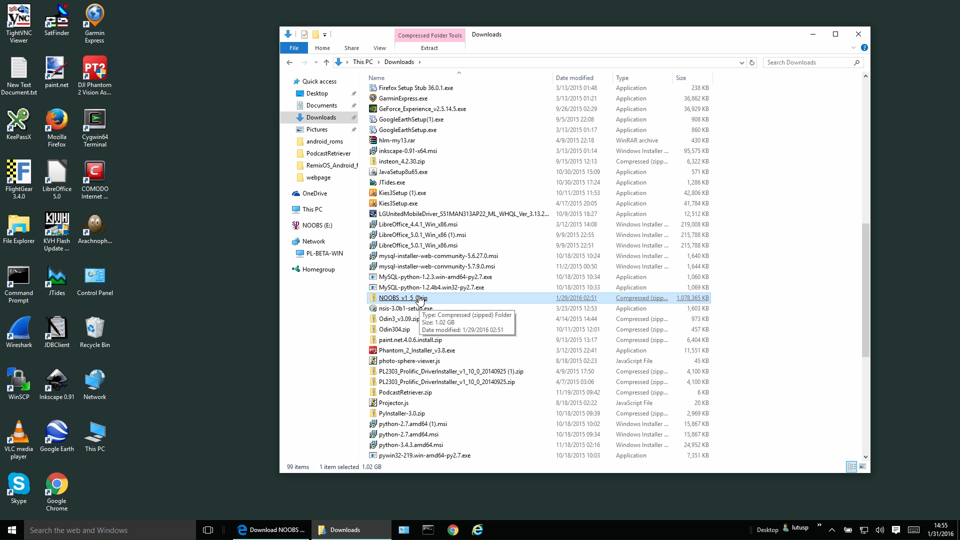
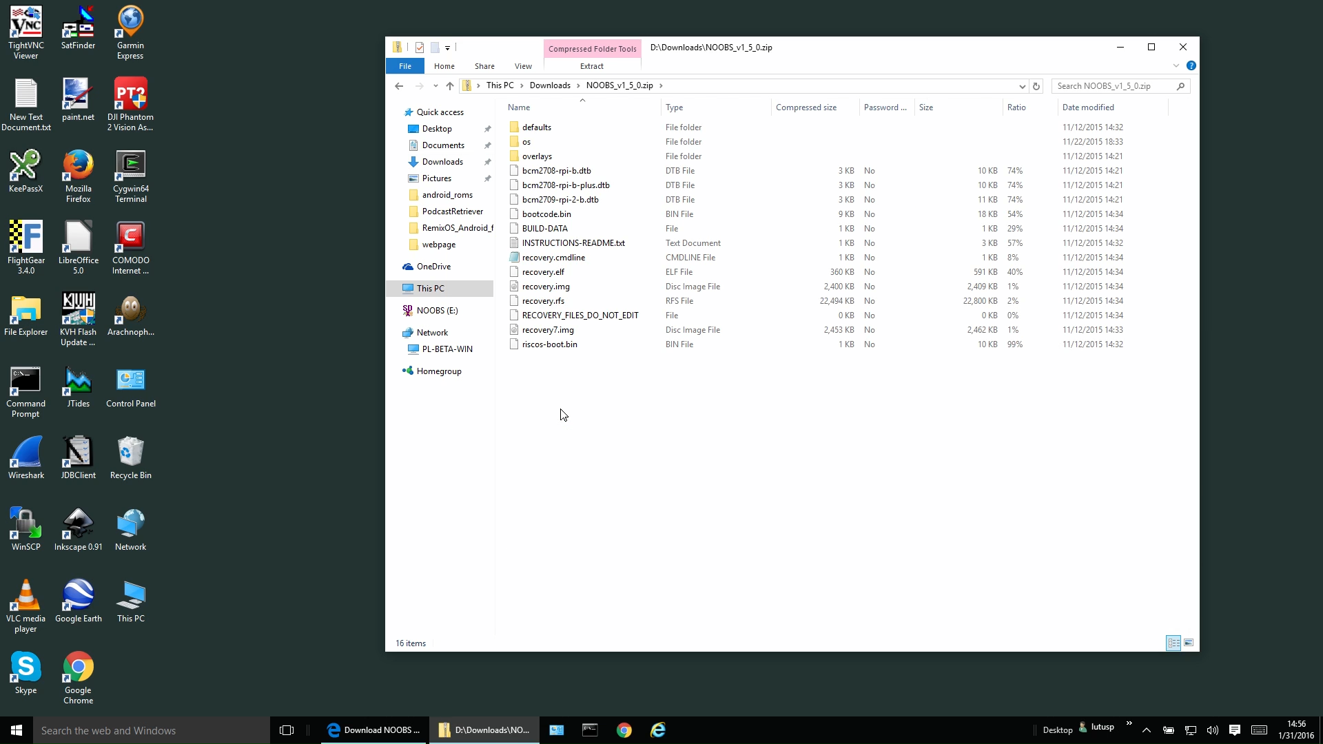
- Locate the downloaded Zip file in your system's downloads directory(graphic) and click it to reveal its contents(graphic).
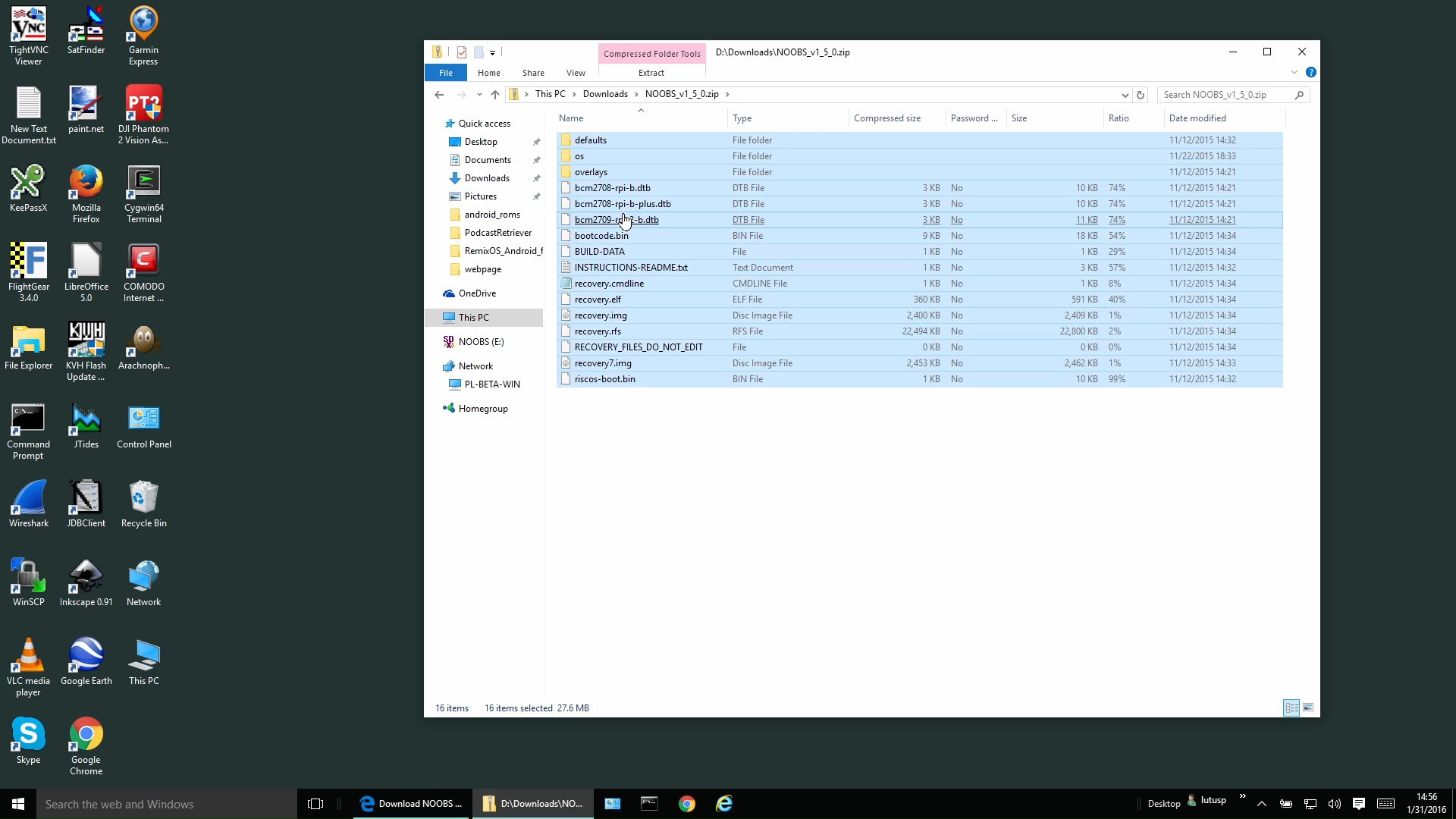
- Select all the contents of the Zip file(graphic) and (by dragging and dropping) copy those contents onto the SD card(graphic). Be sure you're copying the Zip file's contents, not the zip file itself.
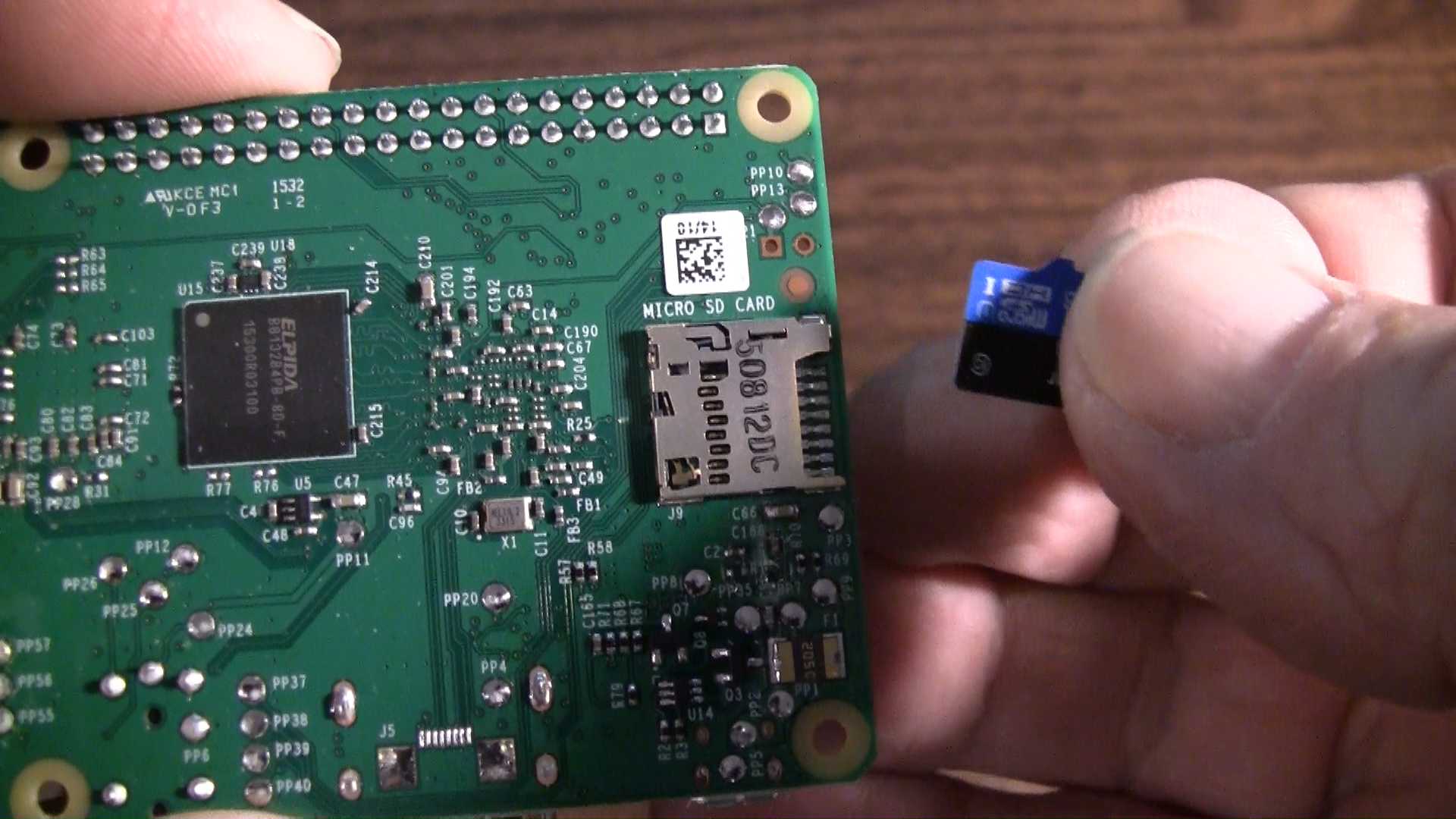
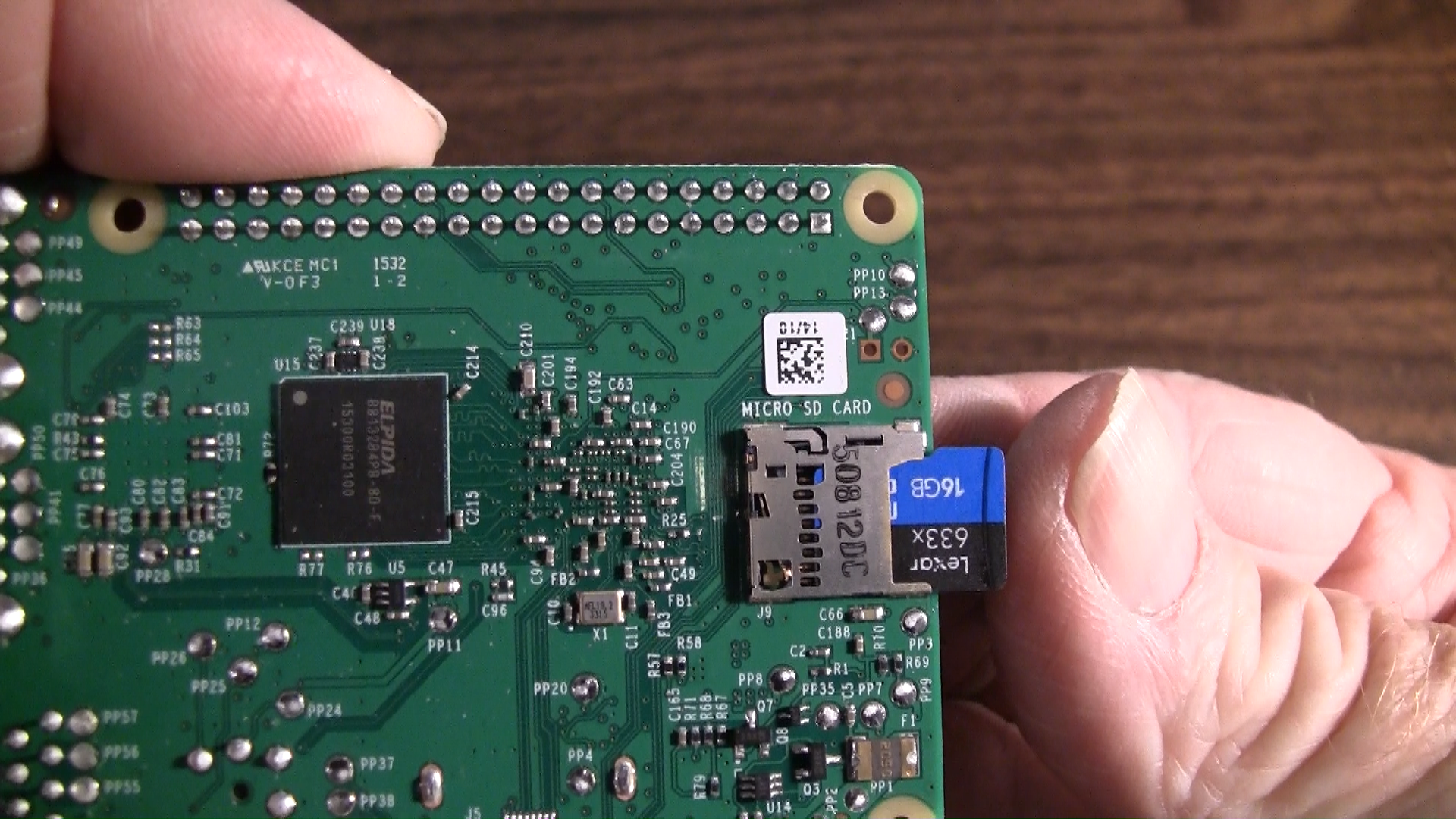
Eject the SD card from your computer — don't just remove the card, tell Windows to eject it(graphic) (this assures that the card has been fully written to and closed).Remove the micro SD card from your computer and insert it into the Raspberry Pi.(graphic),(graphic)
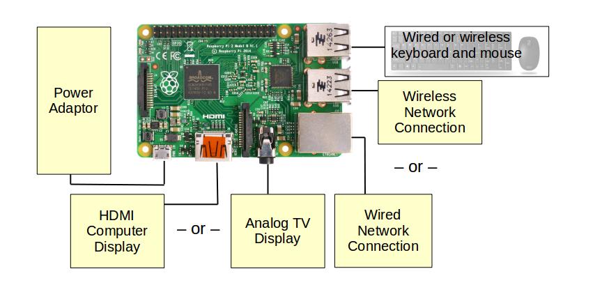
To prepare for first power-up, make the following connections:
Figure 3: Raspberry Pi Connections
Using this approach, you will need either:
- An HDMI-capable TV set or a computer display that supports HDMI, or
- A TV set or computer monitor that accepts an analog signal.
- A USB keyboard and USB mouse. This can be a wireless USB keyboard/mouse combination if available.
- A network cable or USB wireless adaptor, preferably the first.
- The power adaptor that was provided with the Raspberry Pi.
Connect the Raspberry Pi power adaptor to a power outlet.
NOOBS phase:
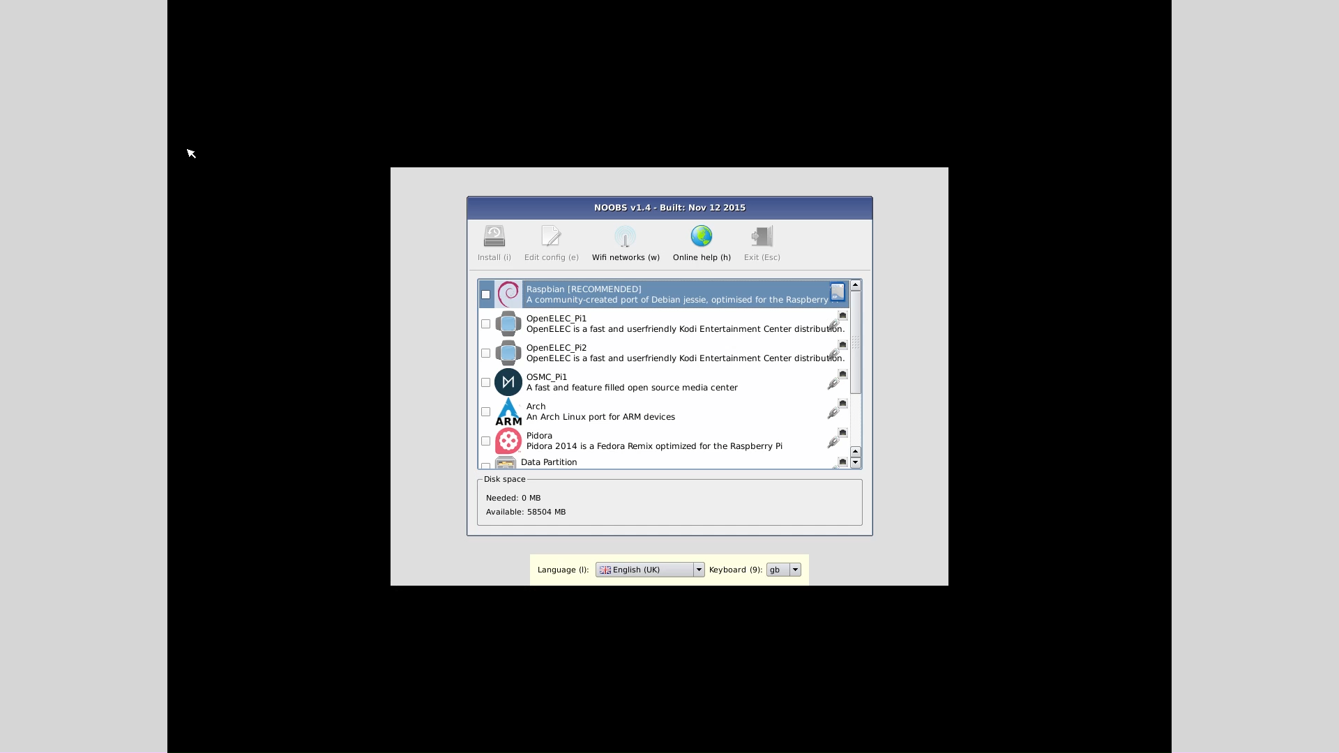
- Having followed the instructions in the prior section, connected and applied power to the Raspberry Pi, readers should see the NOOBS menu on display.(graphic)
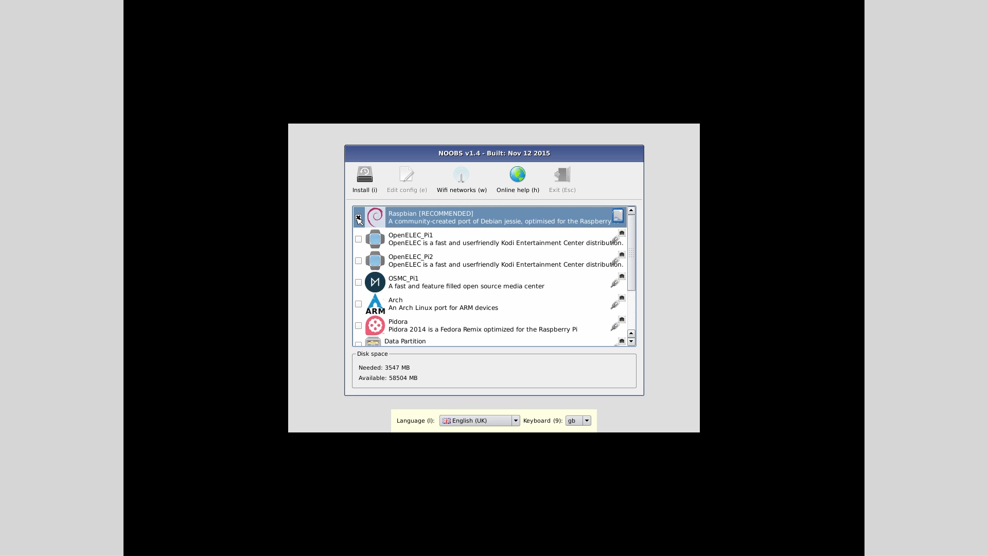
- For this installation, from the menu of choices, select the first item: Raspbian.(graphic)
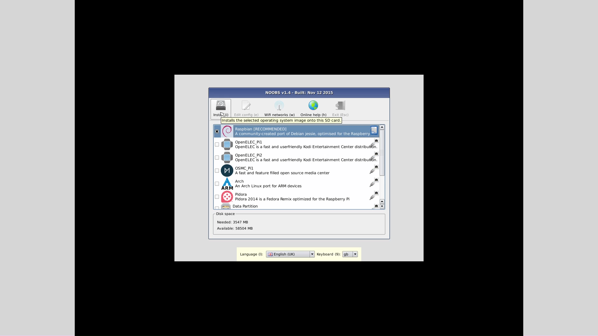
- Begin the Raspbian installation by clicking the install icon at the upper left.(graphic)
- A lengthy, but automatic, installation procedure will follow.
Raspbian phase:
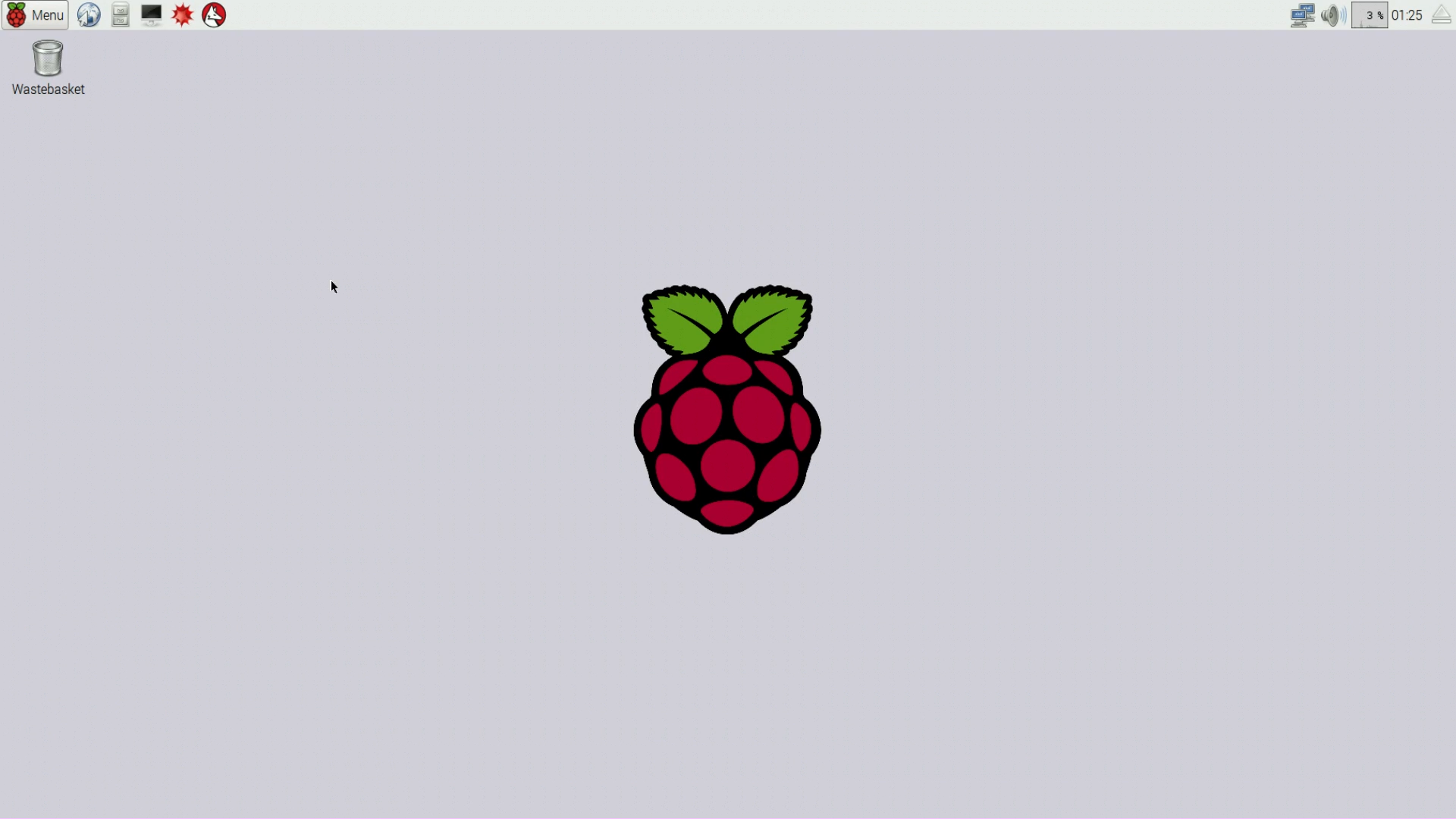
- At the conclusion of the above installation phase, readers should see the initial Raspbian desktop image.(graphic)
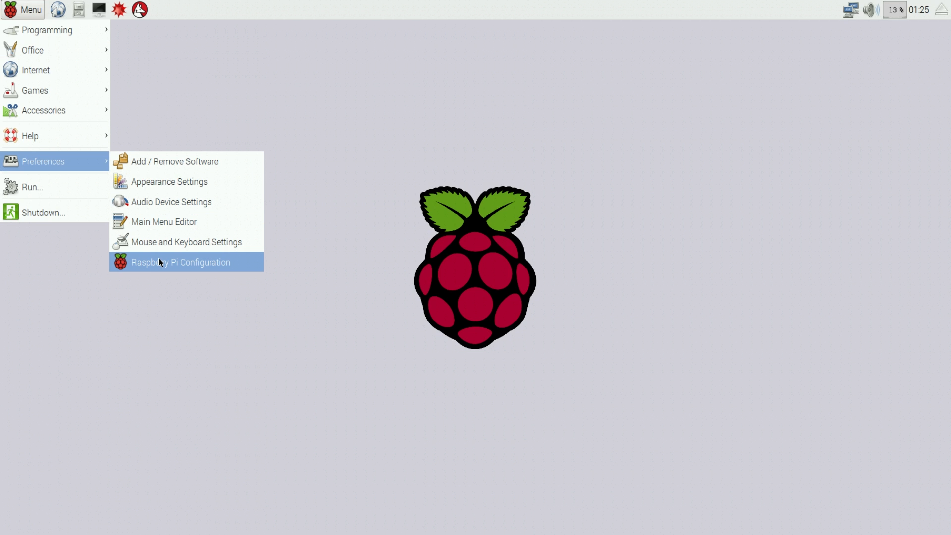
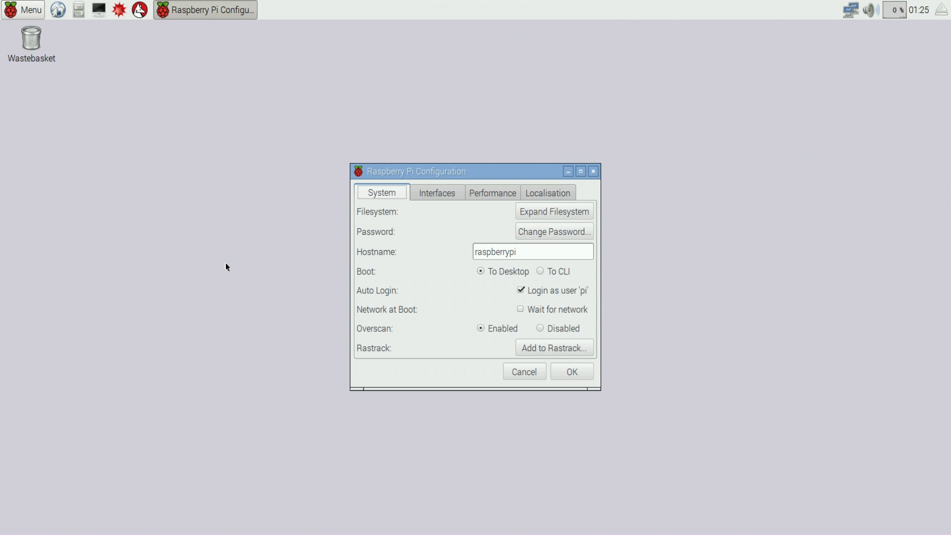
- From this desktop, navigate through the menu tree to the Raspberry Pi Configuration choice(graphic) and launch it.(graphic) Included in the configuration dialog are a number of choices organized in tabs.
- The first desirable function to carry out should be to "Expand Filesystem." This action allows Raspbian to occupy your entire micro SD card for greater storage space. Always take this step before installing additional packages.
- The next settings to make are located on the "Localisation" tab. On this tab, choose an appropriate locale, time zone and keyboard configuration.
- Note: If your Pi has a wireless network adaptor and no wired connection, be sure to enable networking before going on. Click the wireless icon on the taskbar and choose an appropriate wireless access point. Enter a password if required.
CLI phase:
Because we're about to move into an advanced phase, readers may want to explore the Raspbian desktop for a while beforehand. Run some of the available programs, become familiar with your Pi. After you're familiar with the desktop and the menu choices, we can move on.
The "CLI phase" involves launching and interacting with a Command Line Inteface (CLI). It's how we perform in-depth configuration and acquire additional programs and utilities. It's also important to say this phase is optional — the Raspbian environment doesn't require the changes made in this section.
To start this phase:
- Launch a CLI terminal by clicking the terminal icon at the upper left, near the "Menu" icon.(graphic)
- The above action will create a terminal window on your desktop(graphic), a terminal into which we enter typed commands. The terminal window can be enlarged in any of the usual ways — by maximizing it, or by dragging its lower right corner down and to the right.
- To begin using the terminal window, click inside it anywhere to give it focus. Then type a harmless test command — "ls" (meaning "list files and directories") — to see if it's responding correctly:
pi@raspberrypi:~ $ ls Desktop Documents Downloads Music Pictures Public Templates Videos- Now, for some important system checks and upgrades, we must become root (i.e. superuser). After carrying out the following command, be very careful what you type, because by becoming root, you assume complete administrative control over your Pi:
pi@raspberrypi:~ $ sudo su Password: raspberry root@raspberrypi:/home/pi#- Notice that the terminal prompt character has changed from "\$" to "#". According to Linux convention, the character "#" signifies root authority. It may be worth remembering this convention — before typing a command in a CLI, it's wise to establish whether you are (or are not) root.
- Raspbian's developers have created an easy way to upgrade your Pi's firmware if needed — just type "rpi-update" as root:
root@raspberrypi:/home/pi# rpi-update *** Raspberry Pi firmware updater by Hexxeh, enhanced by AndrewS and Dom *** Performing self-update *** Relaunching after update *** Raspberry Pi firmware updater by Hexxeh, enhanced by AndrewS and Dom *** Your firmware is already up to date- For a new Pi, unlike the above example, chances are a very desirable firmware update will take place.
Package management phase:
In this extension of the above CLI phase, we will use a "package manager" to update and upgrade the Raspbian operating system, and optionally install some additional packages and applications.
- Let's start by making sure the locally stored package lists are up to date:
root@raspberrypi:/home/pi# apt-get update (long listing follows)- Now we can upgrade installed packages. This command checks that all installed packages/applications are current and upgrades those that aren't:
root@raspberrypi:/home/pi# apt-get upgrade Reading package lists... Done Building dependency tree Reading state information... Done Calculating upgrade... Done 0 upgraded, 0 newly installed, 0 to remove and 0 not upgraded.- As before, for a new Pi and unlike this example, chances are the above command will produce some upgrade activity.
- Before I introduce two new ways to interact with the Pi, I want to show one more aspect of package management — how to search for and install a new package:
root@raspberrypi:/home/pi# apt-cache search x11vnc ssvnc - Enhanced TightVNC viewer with SSL/SSH tunnel helper x11vnc - VNC server to allow remote access to an existing X session x11vnc-data - data files for x11vnc root@raspberrypi:/home/pi# apt-get install x11vnc Reading package lists... Done Building dependency tree Reading state information... Done x11vnc is already the newest version. 0 upgraded, 0 newly installed, 0 to remove and 0 not upgraded.- I happen to have chosen a package that I've already installed, only to show the syntax: "apt-cache search (package-name)" searches for all packages that include the provided name, and "apt-get install (package-name)" installs a named package on your Pi. These commands will turn out to be very useful in what follows, but online searches using keywords like "apt-get", "apt-cache" and "aptitude" produce many useful references.
Until now we've interacted with the Pi by means of a keyboard, a mouse and a display directly connected to the device — "hard-wired," as computer engineers say. But that's pretty inefficient — wouldn't it be nice if we could interact remotely, through a network connection instead of by wire? Well, we can — by a number of methods. One of these is called "Secure Shell" (SSH for short), and this method is enabled by default in Raspbian. To make an SSH interaction possible, an "SSH client" program is needed on the user's computer. This is probably already true for a Linux desktop machine, but probably not for a Windows machine. Here are instructions for both Linux and Windows (the following assumes your Pi is connected to your local network by a wired or wireless connection):
Linux SSH logon (this example was created on a Linux Mint installation):
To use Secure Shell on Linux, simply open a shell session and type:(desktop shell prompt) $ ssh pi@raspberrypi.local pi@raspberrypi.local's password: raspberry pi@raspberrypi:~ $In the unlikely event that your desktop/laptop Linux system responds to the above with:
-bash: ssh: command not foundThen install the required Secure Shell program with this:
(desktop shell prompt) $ sudo apt-get install openssh-clientAnd repeat the command above.
Once you've made contact with your Pi, skip forward to the section named "Both Linux and Windows".
Windows SSH logon:
To use Secure Shell on a Windows desktop or laptop machine, you will need to install two programs:
A program that enables a network protocol called Zeroconf — a slick way to locate and talk to computers and peripherals on your local network. As it happens, the Pi uses this protocol, Linux uses it, but Windows doesn't. Here's how to install it on Windows:
- Download an installation package from the Apple "print services" support page located here (click the "Download" link).
- (An alternative, more detailed installation procedure is provided here.)
- Run the downloaded program (BonjourPSSetup.exe), deselect both default install options ("Create Bonjour wizard desktop shortcut ..." and "Automatically update Bonjour ..."), and perform the installation.
- To test the Zeroconf installation, open a terminal window (in Windows it's called a "Command prompt") and type:
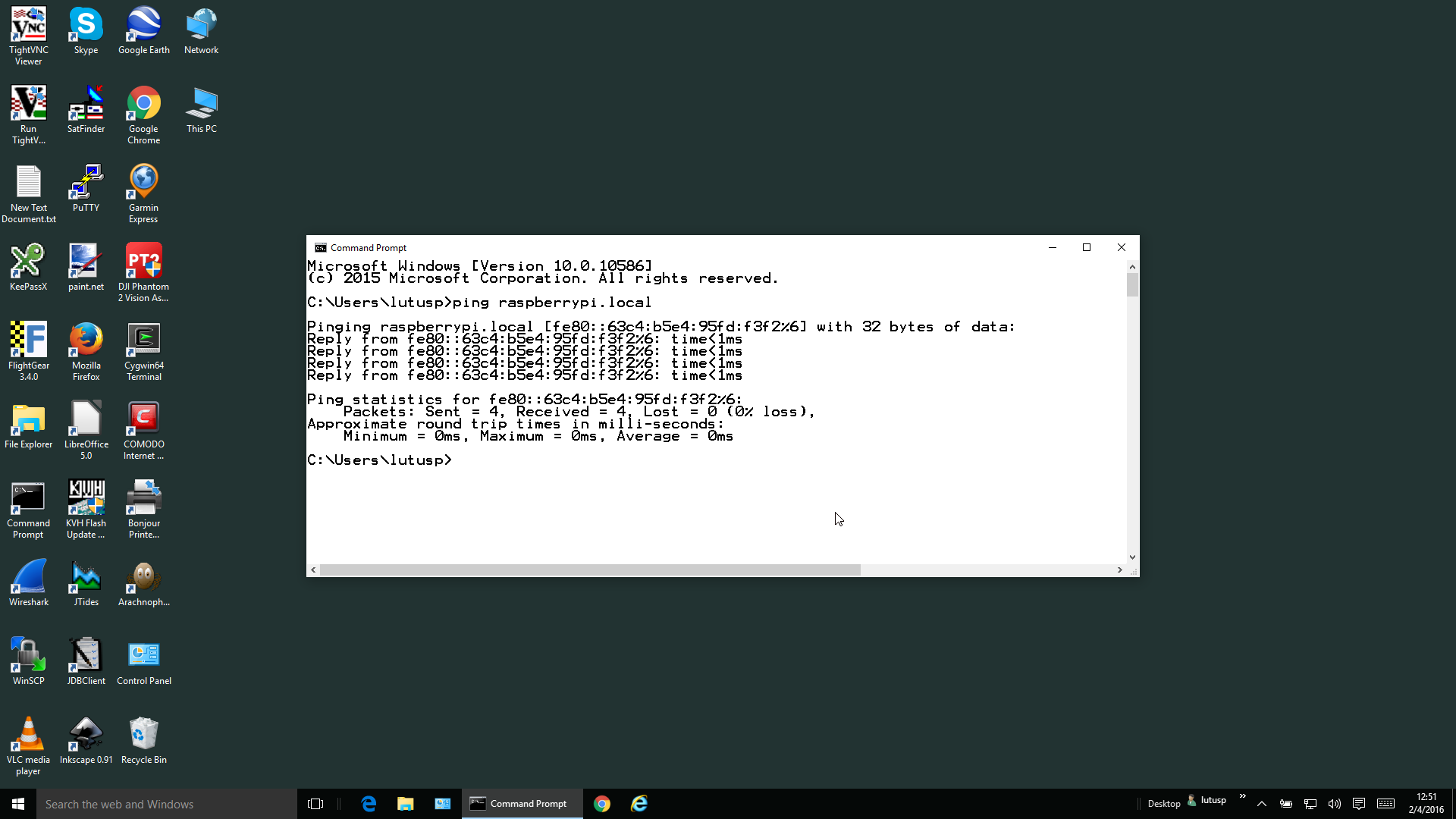
C:\Users\(username)> ping raspberrypi.local- If Zeroconf/Bonjour has been set up correctly, the above command will produce four responses from your Pi starting with "Reply from ...".(graphic)
- If the installation failed, the response will be:
In this event, you may want to make sure the Pi is turned on and connected to your network, and that the above Zeroconf installation was performed correctly.Ping request could not find host raspberrypi.local. Please check the name and try again.A program called an "SSH client". As it happens (just as with Zeroconf), the Pi uses this protocol, Linux uses it, but Windows doesn't. Although there are rumors that Microsoft may eventually add this essential communications tool to Windows itself, in the meantime I recommend that you install PuTTY, a free SSH client program:
- Download a PuTTY executable from the PuTTY download page. This link is the correct one for most current Windows systems.
- Run the downloaded installation program, most likely named "putty-0.66-installer.exe".
- Follow the installation instructions and be sure to accept the desktop shortcut option.
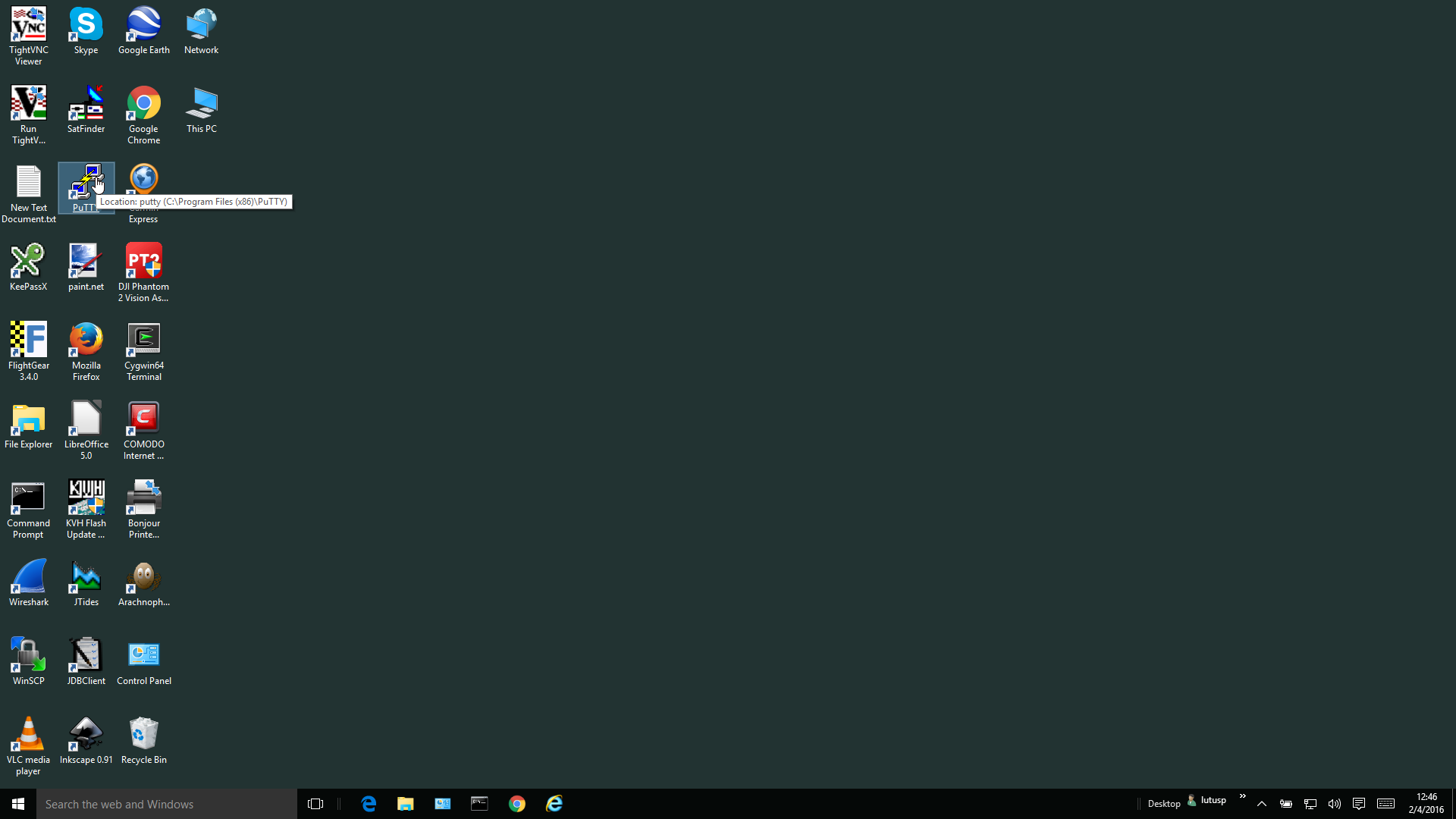
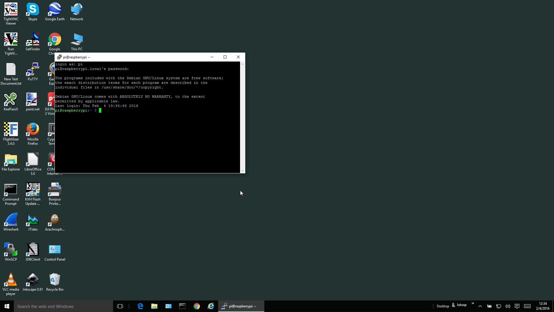
Once you've installed Zeroconf and PuTTY as shown above, click the PuTTY desktop shortcut(graphic) and enter "raspberrypi.local" as the target address(graphic). PuTTY will create a terminal session window and ask for a logon name and password — log on as user "pi" with password "raspberry":(graphic)
login as: pi
pi@raspberrypi.local's password: raspberry
pi@raspberrypi:~ $
Both Linux and Windows:
Now that we've established contact with the Pi remotely, we can use our primary computer's resources rather than requiring a full set of peripherals dedicated to (and attached to) the Pi. It's important to say that this way to communicate with the Pi is available from the time the NOOBS installation phase is finished. The only reason this page has the sequence it does is so readers can become familiar with the Pi in a logical way. After installation is complete, the only absolutely required connections to the Pi are power and network, nothing else.
Working from a desktop or laptop computer has many advantages over typing at a keyboard attached to the Pi. One advantage is that we can easily read instructions from a Web page while typing, or copy text commands from a browser directly into a terminal session, or transfer files from the desktop to the Pi using special commands that are part of the Secure Shell command set.
In the previous section we created a way to communicate with the Pi by way of terminal sessions using typed commands, and did away with the need to have a keyboard, a mouse, or a display connected to the Pi. But there's also a relatively easy way to create remote graphic sessions as well — full interactions with the Pi's graphical desktop from any computer on the local network. I should add that this is an optional enhancement, an "extra". It's not necessary to use your Pi.
Because Virtual Network Computing (VNC) is beyond the essentials of remote interaction, extra programs to support it will need to be installed on the Pi and on Windows, and in some cases on Linux as well. Let's go through them in a logical sequence:
Raspberry Pi:
I've written a script located here to automate installation of a VNC server on the Pi. Using the script requires that it be copied from this website to your Pi, and because of the logistical problems caused by Windows, I have figured out a way to download the file directly from this site to your Pi:
- In a terminal session, log onto your Pi as explained above.
Download the script, in its Zip archive, directly to your Pi like this:
pi@raspberrypi:~ $ wget http://arachnoid.com/raspberry_pi/resources/configureVNC.zipThe above text needs to be entered into a Pi terminal session. To save a lot of typing and avoid errors, do it this way:
- By dragging your mouse cursor, mark the text above from "wget" to the end of the line: "wget http://arachnoid.com/raspberry_pi/resources/configureVNC.zip".
- Point at the marked text, press the right mouse button and choose "Copy".
- On the same machine that received the copy above, enter a Pi terminal session logged on as user "pi", and type Shift-Insert. The copied text should appear in the terminal session window.
- Press Enter to download the Zip archive to your Pi.
Now type:
pi@raspberrypi:~ $ unzip configureVNC.zipThe "unzip" program will respond by extracting a file called "config_vnc_systemd.sh", which you should execute this way:
pi@raspberrypi:~ $ sudo ./config_vnc_systemd.sh- The script will run and, if all goes according to plan, will ask you for a VNC logon password. Don't forget this password — it doesn't need to be the same as your Pi logon password, and if you change your logon password, the VNC logon password won't change.
- If there are no difficulties, at the end of the process the script will print "Done installing VNC server" and exit. At that point the configured VNC server will allow remote Pi desktop sessions.
Linux (this example was created on a Linux Mint installation):
Install a VNC viewer. In a shell session:
(desktop prompt):~ $ sudo apt-get install vinagreIn many cases with Linux distributions, this VNC viewer program will already be installed.
- Run vinagre (which may be listed in the Linux program menus as "Remote Desktop Viewer"), and enter "raspberrypi.local" as the server name. Vinagre will ask for password — enter the password you provided to the VNC server setup script above.
- If all goes according to plan, you will see the Pi desktop graphic interface on display, and your desktop keyboard and mouse will function just as though they were connected to the Pi. Now skip ahead to "VNC Configuration."
Windows:
- For a Windows VNC viewer, install the free distribution of TightVNC Viewer available on this page. For most modern Windows installations, this will be the right download.
- Install the above download in the usual way.
- Run TightVNC Viewer, enter "raspberrypi.local" as a host name and "raspberry" as a password.
- If all goes according to plan, you will see the Pi desktop graphic interface on display, and your desktop keyboard and mouse will function just as though they were connected to the Pi.
VNC Configuration:
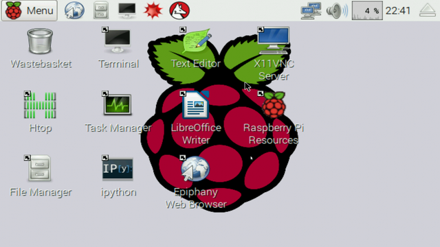
- Once you've installed a VNC server on your Pi and a VNC client on your desktop/laptop, you may want to tune the size of the graphic desktop display that the VNC server presents. This will be especially true if you disconnect any computer display you may have connected to the Pi during an earlier phase of the installation, and run the Pi's VNC server without any display connected. In such a case, the default display will look like this (i.e. small and crowded).
To adjust the display size to better match the size of your desktop/laptop display:
- Find out what your desktop/laptop display size is (different methods will be needed to find these values for Windows and Linux).
Enter a Pi terminal session and type these commands:
pi@raspberrypi:~ $ cd /boot pi@raspberrypi:/boot $ sudo nano config.txt- The above commands will start an editing session on your Pi's boot configuration file. Please be careful while editing this file.
Scroll down using your keyboard's arrow keys to bring these lines into view:
#framebuffer_width=1280
#framebuffer_height=720
Using the width and height you determined for your display earlier (or you may prefer standard values such as width = 1920 and height = 1080), edit these lines so they look like this:
framebuffer_width=(width) framebuffer_height=(height)- Replace (width) and (height) with the values you want.
- Notice in the above edit that the '#' symbols have been removed from the left. This "uncomments" the two lines so they're in effect when the Pi reboots.
- Now, to leave the editor, type Ctrl+X and respond in the affirmative to the question about saving your work.
From the terminal session, reboot the Pi:
pi@raspberrypi:/boot $ sudo reboot- If you've carried out the above edit correctly, the Pi's VNC server display will be correctly sized.
- If there is a black band around the VNC server display and if you would like to get rid of it, un-comment the line in /boot/config.txt that says "disable_overscan=1".
In this section we learn how to access the Pi by way of a file manager, which makes it possible to move files between a laptop/desktop and the Pi, and perform general filesystem tasks. This ability relies on a feature of Secure Shell (SSH) called SSH File Transfer Protocol (SFTP).
This ability is built into Linux as delivered, but as usual it must be added to Windows by way of a third-party application.
Linux:
- To gain access to the SFTP feature, run your favorite Linux file manager (i.e. Dolphin, Nautilus, Nemo, Thunar, etc.), bring the explorer's address / location bar into view, and enter "sftp://raspberrypi.local" into the provided entry window.(graphic)
- In some cases the file manager will ask for a user name and password. For this example enter username "pi" and password "raspberry".
- Most Linux file explorers have a clickable option to show an address / location bar (an editable entry window for a browsing destination) but Nautilus (used in the Gnome desktop environment) requires the user to type Ctrl+L to bring its address / location bar into view.
Windows:
- Windows doesn't support SFTP natively — it must be provided by way of a third-party application that supports it. I recommend the free application WinSCP — click here to download and install a copy.
- To connect to your Pi, click the WinSCP program icon, choose the "New Site" option and enter raspberrypi.local as the host name, "pi" as the user name, and "raspberry" as the password.
- The above should produce a file manager display similar to that seen with a local Windows file manager, with all the same options — move, create and delete files, navigate, open documents.(graphic)
Both:
- Having a file manager available is a great convenience — one can transfer files and folders much more easily than by some of the less intuitive methods shown in earlier sections of this article. During Raspberry Pi software development activities and projects, a file manager greatly simplifies file management activities compared to using terminal sessions.
Pi:
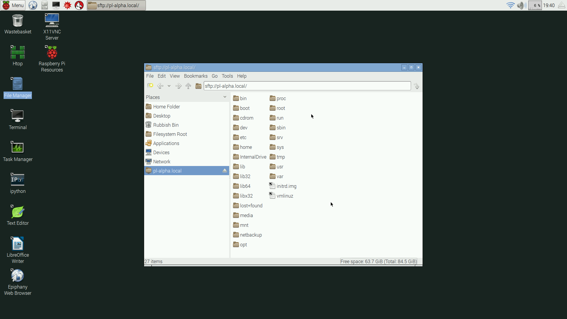
- The SFTP feature is bidirectional — if one is interacting with the Pi's own graphic desktop, either by way of a direct connection or by using the VNC network method described above, one can open the Pi's file manager and access other local network Linux and Windows* computers in the same way explained above — by entering "sftp://(hostname).local" into the file manager's address / location bar.(graphic)
*This Pi-to-desktop SFTP feature works with Windows hosts only after an SSH/SFTP server has been installed in Windows. I recommend OpenSSH for Windows. I would like to say this is an easy point-and-click install, but it's actually rather complicated — here are the details.
One of the Raspberry Pi's unique features is that it provides input-output connections, which open up a world of possibilities for interaction with lights, switches, motors ... and robots. Once I realized this, and in spite of a career spent designing man-rated electronic spacecraft hardware, I revisited a childhood wish to create the 8-bit binary counter described in my introduction, as well as show an example of a Raspberry Pi project that's "easy as Pi". After buying some inexpensive add-on parts and spending a few minutes on assembly, I had this:

Figure 4: Raspberry Pi binary counter breadboard setup (click image for full size)

Figure 5: Raspberry Pi binary counter breadboard setup (closeup) (click image for full size)

Figure 6: Raspberry Pi binary counter breadboard circuit diagram (click image for original PDF)
Figure 7: Python binary counter program listing (click here for downloadable plain-text source)Sequential Counter
I've written a different version of the above code that uses the same hardware setup, but that increments the counter over time and doesn't accept user input, so it's not as interesting as this project. I include it just to provide another code example that drives a set of eight LEDs in a binary counter configuration. Here's the link.
This project requires less circuitry but more mental work than the prior input/output example. As before, it takes advantage of the Pi's input/output connections, but it does something more interesting with them.
Theory
The Pi's input/output connections are digital — they're either on or off, either one or zero. Doesn't this prevent their use for audio generation? After all, an audio signal must assume many levels intermediate between one and zero. As it turns out, there's a method called pulse-width modulation that can produce any number of intermediate levels from a digital source. In this project, I'll show how to generate an analog signal from the Pi's digital outputs. (The Pi has a normal audio output available, but we'll disregard that for now.)
Let's say we want an output level of 1 volt from a 5 volt logic output gate. Since we can't simply reduce the voltage at which the logic gate operates, we have to think of another way to change the level. How about a scheme that turns the gate on and off very quickly, in such a way that the gate is on for only 10% of the time? Wouldn't that create an average level of 1 volt? Well, yes, and that's how pulse-width modulation works.
Here are logic gate output graphs showing 80% and 20% duty cycle (meaning percentage of time activated) waveforms:


Figure 7: pulse width duty cycle examples
If average values were taken of the above waveforms, the 80% waveform would produce 4 volts and the 20% waveform would produce 1 volt. And there are easy ways to convert such waveforms into average values, the most common being an RC integrator (or RC low-pass filter):
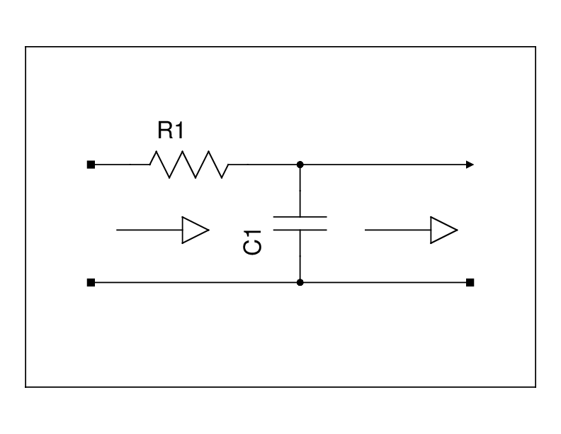

Figure 8 : 80% duty cycle conversion example

Figure 9 : 20% duty cycle conversion example
Implementation
So that's the basic idea behind pulse-width modulation. Now let's think of a way to create a converter that will accept a normal audio waveform and produce a pulse-width modulated signal as shown above. Here's one way (there are others) — we could compare a high-frequency sawtooth waveform to a low-frequency audio waveform. At times when the audio waveform was more positive than the sawtooth waveform, the logic gate would be set high, otherwise low. The scheme would look like this:

Figure 10: Audio/sawtooth mixer inputs
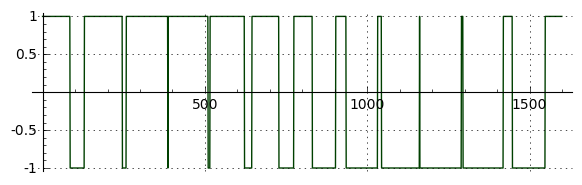
Figure 11: Audio/sawtooth mixer output
Okay, the theory seems valid in principle, but how does this work in practice? Well, I know from experience that it works very well in high-speed circuits where there's a large difference between the audio and conversion frequencies. But if the conversion frequency is close to the audio frequency, certain problems come up, most having to do with a classic signal-processing limitation called the Nyquist–Shannon sampling theorem, which says the sampling rate in a scheme like this must be at least twice the maximum expected signal frequency. In this example the sawtooth waveform's frequency determines the sampling rate.
Practical Example
Using the Raspberry Pi's input/output connections and a little Python code, and in spite of Python's relatively slow execution speed, I was able to create a working example of the scheme diagrammed above. It's only meant to demonstrate pulse-width modulation and serve an educational purpose, not be a practical solution — for that we would need much faster code than Python can provide.
Here's the circuit diagram for this example (the oscilloscope is optional but useful for debugging):Here's the Python program listing:
Figure 12: Pulse-width modulation circuit diagram (click image for original PDF)
Figure 13: Pulse-width modulation program listing (click here for downloadable plain-text source)During this project I synchronized my oscilloscope with a logic reference signal that provided the zero crossings of the test signal, which was a 440 Hz (middle A) sinewave. This synchronization allowed me to stabilize the display of the pulse-width modulation signal:
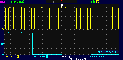
Figure 14: Oscilloscope display
Upper trace: Pulse-width signal
Lower trace: sync signalThe expected pulse-width pattern, following the audio signal's waveform, can be clearly seen in the upper trace. Here's a picture of the experimental setup:

Figure 15: Pulse-width modulation experimental setup (click image for full size)
(Astute observers will notice that I carried out this measurement without tearing down the binary counter circuit from the previous example.)
Here's an MP3 audio sample of the pulse-width modulated experimental output, captured on my desktop machine from the breadboard circuit. In the recording, some incidental signals can be heard, like the Raspberry Pi processing interrupts, and noise resulting from the informal breadboard layout. In spite of those limitations, and in spite of the absence of an output low-pass filter, the 440 Hz sinewave test signal is surprisingly clear. When headphones are connected to the breadboard, the result is much like the recording — a reasonable recreation of the original test signal along with various noises resulting from the fact that Linux is interrupt-driven and can't spend every moment of its time on our program.
Some History
This project reminds me of another of my projects from many years ago, written on an Apple II. In that computer there was no sound card and no way to create music, just a speaker attached to a logic gate that could make a "beep" sound. At first, the prospect for creating any pleasant sounds seemed unlikely.
But by the time I acquired my Apple II I was reasonably skilled at electronic circuit design and I knew a bit about signal processing, so I wrote a program in Apple II assembly language that used the same methods described in this project to play — not just reasonable sounding music — but music with two voices at once, from a single logic gate. That program, named "Electric Duet," made a lot of people happy and was a nice activity. Here's a more detailed account of that project.
Description
This is a more practical input/output example — it uses the Raspberry Pi GPIO section to drive a relay. The idea of a relay driver (and a relay) is to support higher-powered loads than the Pi can handle on its own. In my example circuit, a commonly available five volt reed relay is activated by the Pi by way of a driver transistor that energizes the relay's magnetic coil. A larger, higher-current relay can be used in this circuit, but larger relays might need to be powered by a higher powered source than the Pi itself, as in this example. Here's my experimental setup:

Figure 16: Relay driver experimental setup (click image for full size)
Here's the scope image for this driver circuit:
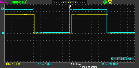
Figure 17: Relay driver scope traces
Blue trace: Raspberry Pi driving signal
Yellow trace: Relay contactsNote the horizontal time scale in the above scope trace picture: one millisecond per major division. On that basis and by careful examination of the scope traces, it seems the relay is responding in about 300 µs. For the above picture I set the cycle rate to five milliseconds, which a small, low-mass reed relay has no problem keeping up with. A larger relay would probably not only not be able to keep up, but would likely be worn out in a short time by this activation rate.
Here's the circuit diagram for this example:

Figure 18: Relay driver circuit diagram (click image for original PDF)
Circuit notes
This circuit differs from my other examples in an important way — a user may want to connect a high-voltage, high-power load to the relay. Because of this, I want to warn people who have only a little experience with electronics that house current can be deadly and the right-hand section of Figure 18 should be handled very carefully. In fact, I designed this circuit to be self-indicating — the parts in the dashed box labeled "Optional components" aren't really needed for the circuit to function, but can be used to show that the relay has been activated without needing to have a load connected. I recommend this arrangement for preliminary testing, to avoid the risk of electric shock.
Spike suppression
When the relay is deactivated, the collapsing magnetic field produces a large positive voltage spike which might destroy the driving transistor. This outcome is prevented by diode D1, which absorbs the voltage excursion before it can destroy NPN1. Driving circuits of this kind should always include a spike suppression diode. Here's what the diode accomplishes:
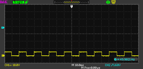
Figure 19: Voltage across relay coil with suppression diode D1
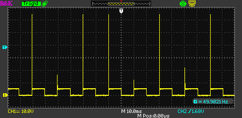
Figure 20: Voltage across relay coil with no suppression
(About 65 volts generated by a 5 volt circuit.)Python Code
Here's the Python program listing:
Figure 21: Relay driver Python code listing (click here for downloadable plain-text source)
The Python program is just for testing and to show how to configure the Pi to drive the relay. The program cycles the relay on and off with a time delay determined by variable time_delay, units of seconds. This variable can be given a value < 1, for example in one extreme test I set it to 0.001, or one millisecond, just to see if the reed relay could keep up (result: sort of).
I want to expand my description of the Zeroconf/Bonjour network configuration protocol that plays a part in most of the topics above.
- Zeroconf/Bonjour is a rather slick auto-configuration (or "zero configuration") network protocol that helps computers, printers and other devices find and negotiate with each other.
- The basic idea of Zeroconf name resolution is that if a host or peripheral has the suffix ".local" appended to its name, the system knows it's a Zeroconf name and the task of locating the device is assigned to Zeroconf.
- To create a plain-text list of all the hosts and devices that Zeroconf knows about, from a Linux terminal session type:
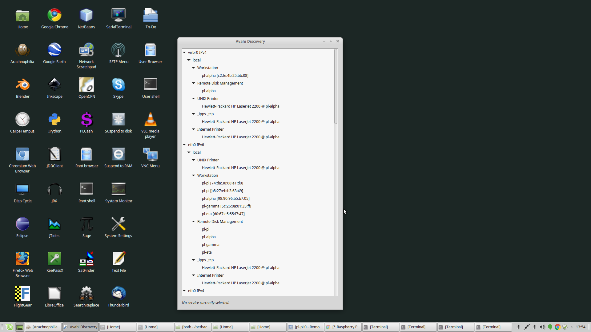
(desktop prompt) $ avahi-browse -at (long list of hosts and services)- Another way to get a Zeroconf list on Linux is to examine the desktop menu tree for an application named "Avahi-discover".(graphic)
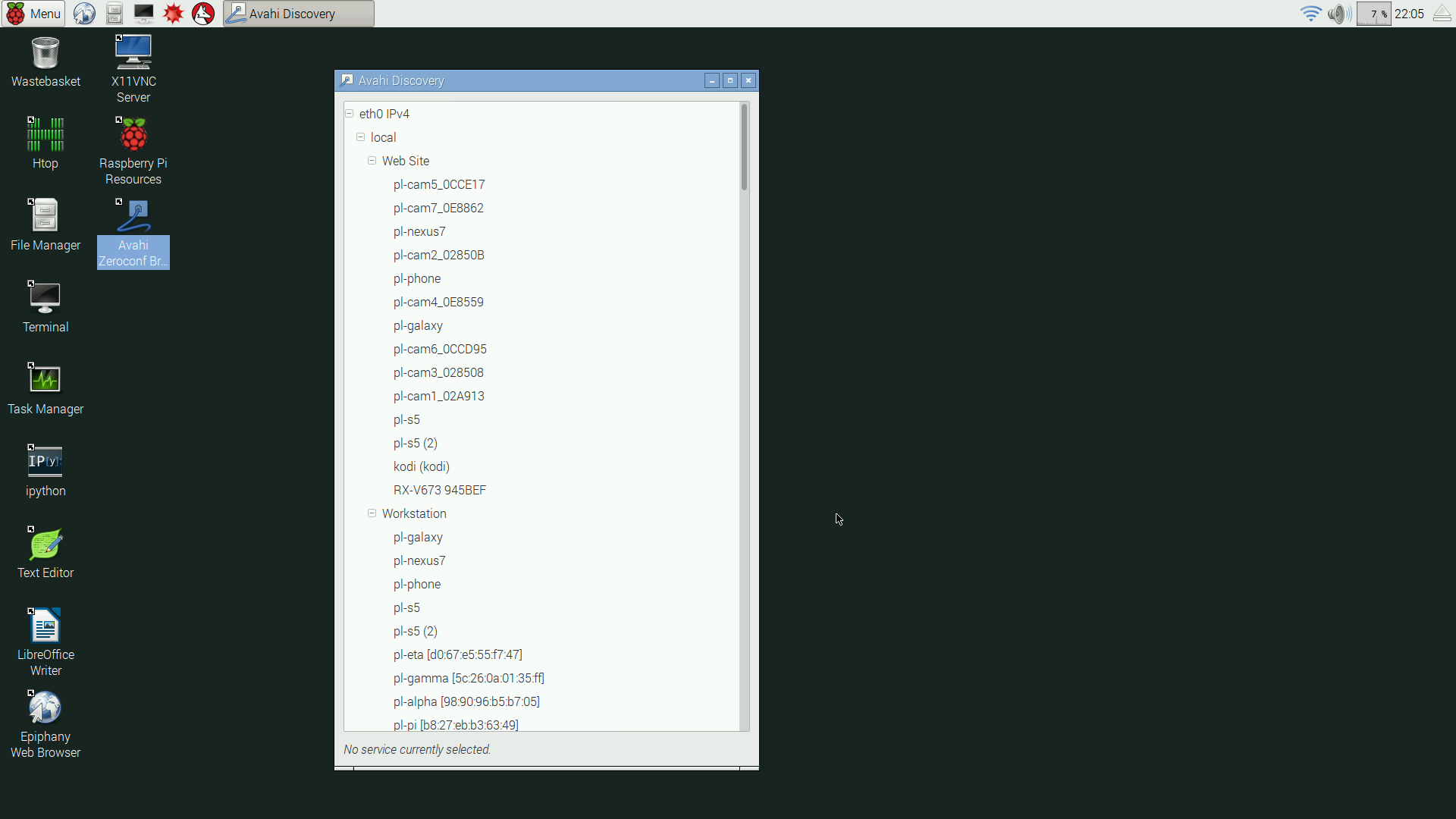
- The above "Avahi-discover" Zeroconf-list application works exactly the same way on the Pi.(graphic)
Zeroconf Installation issues:
- The Raspberry Pi has Zeroconf installed by default, so once a Pi is running on your local network, from a Linux machine you should be able to find it by its name, which by default is "raspberrypi.local":
(desktop prompt) $ ping -c 1 raspberrypi.local PING raspberrypi.local (192.168.0.118) 56(84) bytes of data. 64 bytes from 192.168.0.118: icmp_seq=1 ttl=64 time=0.258 ms --- pl-pi.local ping statistics --- 1 packets transmitted, 1 received, 0% packet loss, time 0ms rtt min/avg/max/mdev = 0.258/0.258/0.258/0.000 ms- If a Linux machine cannot locate a connected and running Raspberry Pi by name, make sure the Linux machine has Zeroconf installed (most modern Linux distributions have Zeroconf installed and running by default):
(desktop prompt) $ sudo apt-get install avahi-daemon avahi-discover libnss-mdns (installation reply)- If a Windows machine cannot locate a a connected and running Raspberry Pi by name, it's likely to result from the fact that Windows has no native support for Zeroconf. To solve this problem, download and install the Apple Print Services utility available here. Be careful while installing this utility — unless instructed not to, it tries to install and start additional services you almost certainly do not want.
One remedy for the aggressive behavior of the above installer is to open the executable as an archive and extract only the Bonjour installer component, then run only that component:
- Right-click the BonjourPSSetup.exe installation program, then choose "Extract to BonjourPSSetup\".
- Move to the newly created directory "BonjourPSSetup".
- In this directory, click Bonjour64.msi to install Zeroconf and nothing else.
Conclusion
It's my hope that, because of its high value and because it's free, Zeroconf will become a standard feature of computers on local networks (for Linux machines, this goal is already achieved). It greatly simplifies network management compared to things I've tried in the past, a topic I explore at greater length in this article.
This is a collection of short, useful items having to do with setup, troubleshooting and configuration.
Linux: flash SD card using dd
There is a particular way this should be done, and it helps to know why it works ... when it does work.
The purpose of flashing an SD card is to directly create a bootable SD/micro-SD card containing a preconfigured operating system. This method avoids the time-consuming process of creating a NOOBS install disk, then watching the NOOBS algorithm create a bootable disk for you. Here are the steps:
- Acquire a flashable operating-system image, example Raspbian. Be sure to unzip/unpack the downloaded archive for the steps below — in other words, make sure you have an ".img" file ready.
- Acquire one or more SD/micro-SD cards that are known to work with the Raspberry Pi. Read this article, or one like it, to see which cards are likely to work.
- Insert your SD card into a desktop/laptop computer running Linux. When you do this, the card should be automatically assigned a device node.
- To determine the assigned device node(s) with a minimum of confusion, use the command "lsblk" to list all block devices. If there's any doubt about the identity of the SD card in the list, try running "lsblk" before and after inserting the card — the device node(s) that are only present while the card is inserted are its nodes.
- Better and more fun than the above, we can make "lsblk" run repeatedly at one-second intervals, then insert the SD card to see the list change dynamically. Like this:
(desktop prompt):~ $ while true ; do lsblk ; sleep 1 ; done- Having determined which device node(s) represent the SD card, we're ready to flash an operating system image.
- There are two points to remember about the flashing process:
- It doesn't matter what's on the card initially, because it's going to be completely erased. So don't bother creating and formatting partitions, or creating a new partition table, that's a waste of time.
- The target for the flash process is the raw device, not one of its partitions. A raw device is identified by /dev/sdX (X = specific assigned device letter), while the first partition on the device would be identified by /dev/sdX1. The flash method being described must be performed on /dev/sdX, not /dev/sdX(n).
- At this point we should have an operating system image file with a suffix of ".img", an SD/micro-SD card, and a Linux desktop/laptop machine on which to perform the flash. Here are the instructions to perform the flash:
(desktop prompt):~ $ sudo dd if=(OS image file name).img of=(device node, example /dev/sdz) bs=32M (desktop prompt):~ $ sync- Always include the "sync" step after the "dd" copying program finishes the flash operation, to make sure that pending writes are completed.
- Now you can take the SD card out of the desktop/laptop and attach it to the Pi.
Linux: Boot Problems
If your Raspberry Pi won't boot, I have a reasonably effective troubleshooting procedure. It's based on logic and the systematic elimination of causes.
- First, make sure your Pi is connected to a reliable power source that can deliver at least 1 ampere at 5 volts. In normal circumstances a Raspberry Pi 2 model B draws at most 0.5 ampere with a full set of connected peripherals, but if there are boot problems, it's logical to try to eliminate the power source as an issue.
- Second, remove all attached peripherals — USB devices, mouse, keyboard, and monitor connection (unless you already know the monitor can be relied on to provide some kind of display).
- Third, remember that a Raspberry Pi running Raspbian supports both Zeroconf and Secure Shell, so it's worthwhile to try to log onto the Pi from a Linux desktop that's also running Zeroconf and has a Secure Shell client program available (most modern Linux distributions have these). After powering the Pi, connect a wired-network cable (don't try to use a wireless USB adaptor at this stage) and from a Linux desktop machine try this:
(desktop prompt):~ $ ping raspberrypi.local- If that succeeds, try this:
(desktop prompt):~ $ ssh pi@raspberrypi.local (password raspberry)This assumes that Raspbian is the OS on the SD card and that none of the initial values have been changed.
- If both the above steps succeeds, you're logged onto the Pi, so start monitoring the system error log:
pi@raspberrypi:~ $ sudo tail -f /var/log/syslogOnce having begun monitoring the system log, you can start connecting and disconnecting peripherals to see if one of them is causing difficulty.
Photosensitivity
There's a truly bizarre property of the Raspberry Pi 2 model B — if a strong light source (camera flash, laser pen) is shone at a particular location on the board, the machine will lock up. Here's a picture of the sensitive component (it's between the HDMI and power connectors, which are just visible along the lower edge of the graphic):
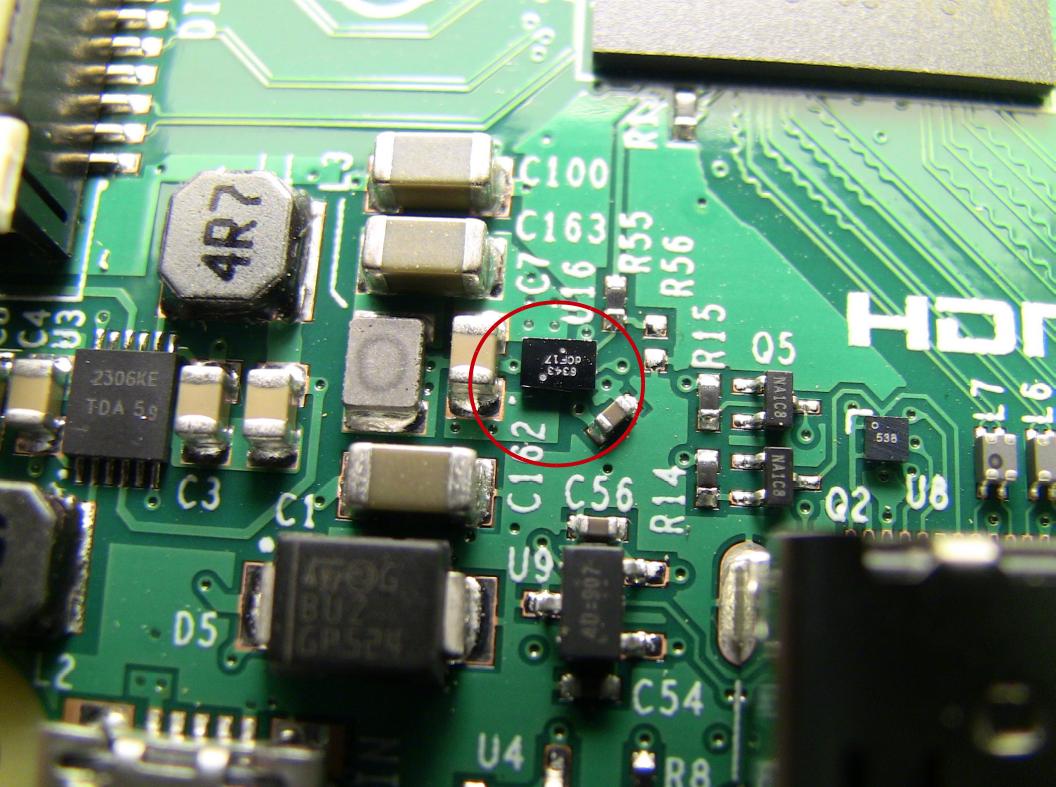
Figure 22: location of photosensitive component
I've found that a bright green laser pen, shone directly at the sensitive component, is enough to lock up the Pi. I mention this because if there are boot or stability problems, bright lights are another thing to avoid.
Text-Interface Mode
There may be times when one may wish to disable the Raspberry Pi's graphical interface and apply the saved memory and processor resources to some other purpose. Or it might be that a user wants to apply the Pi to a special role that doesn't require the graphical interface, for example as a small unattended server.
It turns out that Raspbian has a text-based configuration program that can be used to disable and enable its graphical interface, so one isn't left locked out by disabling the desktop. Here are the steps:
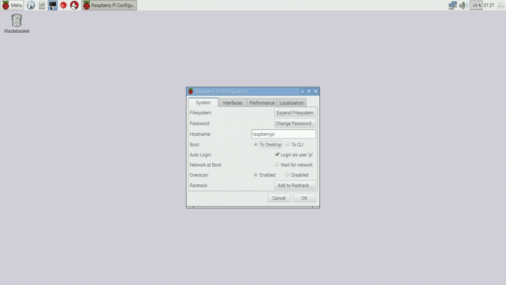
- To disable the graphical desktop and create a text-only logon, from the desktop menu tree select Preferences ... Raspberry Pi Configuration. Select the System tab and enable the "Boot to CLI" option.(graphic) Reboot the Pi.
To re-enable the graphical desktop after having disabled it, log onto the Pi from a desktop or laptop machine using Secure Shell and enter:
pi@raspberrypi:~ $ sudo raspi-configThe above will open a text-based menu program that offers a number of choices including "Boot Options".(graphic) Choose "Boot Options" and select either "Desktop" or "Desktop with autologin". Reboot the Pi.
- It may be obvious at this point, but just in case, the process of both disabling and enabling the graphical desktop can be carried out using only the text-based configuration program — it's not necessary to use the desktop-based configuration utility.
Again, the above configuration can be used to conserve system resources as well as allow the Pi to execute some processes more quickly because it doesn't have to support the desktop environment. It may come as a surprise to some of my younger readers but there was a time, not very long ago, when all computers had text-based interfaces, and the idea of a graphical desktop was someone's idle fantasy.
Wireless blues
Raspberry Pi owners often buy a particular USB wireless adaptor, one that has a weird behavior — it automatically turns itself off after a short time. The component's maker is Edimax, and, apart from this one quirk, people seem to find it to be a terrific product (as I do).
Again, the problem is that the adaptor shuts itself down after a short time, so if it's the only network connection, the Raspberry Pi disappears from the network. Here's the remedy:
- Download this small file and make a copy on your Pi at /etc/modprobe.d/8192cu.conf.
- Reboot the Pi.
Problem solved, but this change means more power usage, because the wireless adaptor won't automatically turn itself off any more. By the way, on the topic of power issues ...
Raspberry Pi Power Issues
There's been a lot of discussion online about how to power the Raspberry Pi, which power sources can be relied on and which cannot, but many of the discussions are misinformed. Much is made of acquiring a high-current power source, like 2 amperes or more, for proper operation. Before writing this section I performed some tests and I have some results that may surprise the "experts".
- There's a consistent difference between the source voltage (measured at the power source) and the voltage at the Pi's USB ports, of about .1 volt. Because of the Pi's small current requirements, this voltage difference is only partly explained by line drops.
- The Pi's red power light is set up to extinguish at an input voltage of about 4.9 volts (which produces about 4.8 volts at the USB ports).
- The fact that the power LED extinguishes during normal operation is causing Pi owners a lot of anxiety, but after some tests and in my opinion, there's little cause for alarm.
- Notwithstanding this scheme that causes the power light to extinguish, the Pi continues to reliably operate all the way down to 3.9 volts or possibly less (my power supply isn't adjustable below this voltage).
- This means that solving the power-light problem by buying high-current power supplies is pointless, unless users are powering high-current USB peripherals attached to the Pi with no independent power sources of their own.
- Here are some measured currents correlated with attached devices:
Connected Peripherals Measured Current Amperes None. No USB devices, no wired network connection, no monitor connection. Only a power connection. 0.214 Wired network connection, plus three USB peripherals (wireless adaptor, wireless keyboard, Bluetooth adaptor), plus an HDMI monitor connection. 0.362 All the above plus a 128GB USB SSD storage device — no more ports available. 0.5 The third table entry above, the "full house" with all ports occupied, will likely cause the Pi's red power light to extinguish if the device is powered by a USB hub, but only because a typical hub's output voltage will fall to 4.9 volts under those circumstances, not because it's unable to provide enough power to reliably operate the Pi. My recently acquired, rather exotic USB 3.0 hub, with a power pack able to deliver 4 amps, couldn't keep the Raspberry Pi's red power LED lit during the third phase of the above test, only because the voltage at the Pi fell to 4.9 volts under a 0.5 amp load.
My conclusion? If Raspberry Pi owners want to keep the red power light constantly lit, they should acquire a power source able to deliver more than 5 volts all the time. But if people are concerned about reliable operation, as long as the Pi's source voltage stays above about 4.5 volts and the Pi is not being required to power any demanding peripherals without assistance, this is a tempest in a teapot.
The short form: it's not about current, it's about voltage, and unless you have high-current peripherals attached to your Pi, it's not about anything.
VNC on the Pi
In Raspbian as delivered, Secure Shell is enabled, Zeroconf is enabled, but VNC isn't — it's not even installed. I think this is a shame — a VNC server doesn't take up much space or processing power when it's not active, it's a bit difficult for untrained users to install and activate, and it's a terrific way to gain access to the Pi's graphical desktop from a local-network desktop or laptop, without having to connect a USB keyboard, mouse and HDMI monitor directly to the Pi.One reason for the absence of VNC in Raspbian might be that Windows also doesn't have it installed, and most people who acquire a Raspberry Pi are Windows users. That is also a shame, but installing a VNC viewer on Windows is easy and free.
I hope the Raspbian maintainers will consider the idea of adding a VNC server to a future distribution — I think it adds more than it takes away.
About Microsoft Windows
While reading this article, readers may have noticed something — if they make a list of nice operating system features, productive tools and utilities that make life easy for network administrators (Secure Shell, Zeroconf, VNC), they may notice that Linux comes with all of them, but Windows comes with none of them. I can make Windows support each of these features, but it's not easy, and with respect to Secure Shell, a feature most computer professionals regard as essential, the configuration process required to make it function on Windows is truly baroque and well beyond the skill level of the average computer user.
Why is this? Why is Microsoft trying so hard to make life difficult for people? One answer requires some understanding of Microsoft's history. There was a time, not very long ago, when Microsoft believed Windows to be the only operating system choice, so it didn't matter what they did, they weren't accountable. Those days are over, but it seems Microsoft hasn't adjusted to today's reality.
People at Microsoft may think if they support features that make communication with Linux machines too easy, that might become the first move down a slippery slope — toward replacing Windows with Linux. But I would argue that the present policy, in which obviously useful operating system features are locked out, might accelerate that process more dramatically than including them.
In the long term this topic may seem a bit silly, since Microsoft is clearly doomed — it can't possibly compete with free operating systems that offer better value and more reliability than Windows — but in the short term it's painful to watch Microsoft's gradual disintegration.
From time to time my neighbor, an intelligent end user with Windows 10 installed on his machines, calls me up to complain that his backup procedure has failed again. Then I visit, plug in his backup USB drive, and watch Windows assign a totally random drive letter to the device.
My neighbor's backup program needs drive letters to locate source and destination backup drives, but Windows won't assign consistent drive letters. Consequently, my neighbor can't ever be sure he's made the backup he thinks he has, from a specific drive, to another specific drive.*
Then I look at the calendar, realize it's 2016, and I say, "I can't f**cking believe this — people are paying Microsoft money to be abused this way."Thanks for visiting, and thanks for reading.
| Home | | Raspberry Pi | | | Share This Page |

